Husky HME-423E, HME-421E user manual Wiring The Fault Alarm Contact, Cabling

Models: HME-423E HME-421E

1 77
Download 77 pages 56.55 Kb
Page 13
Image 13
2-5.3 Wiring The Fault Alarm Contact

Hardware Installations

The acceptable wire range is 12 to 24 AWG.

After the wiring the power inputs, the PWR LED will light up. Please refer to LED Indicators section for more information.

2-5.3 Wiring The Fault Alarm Contact

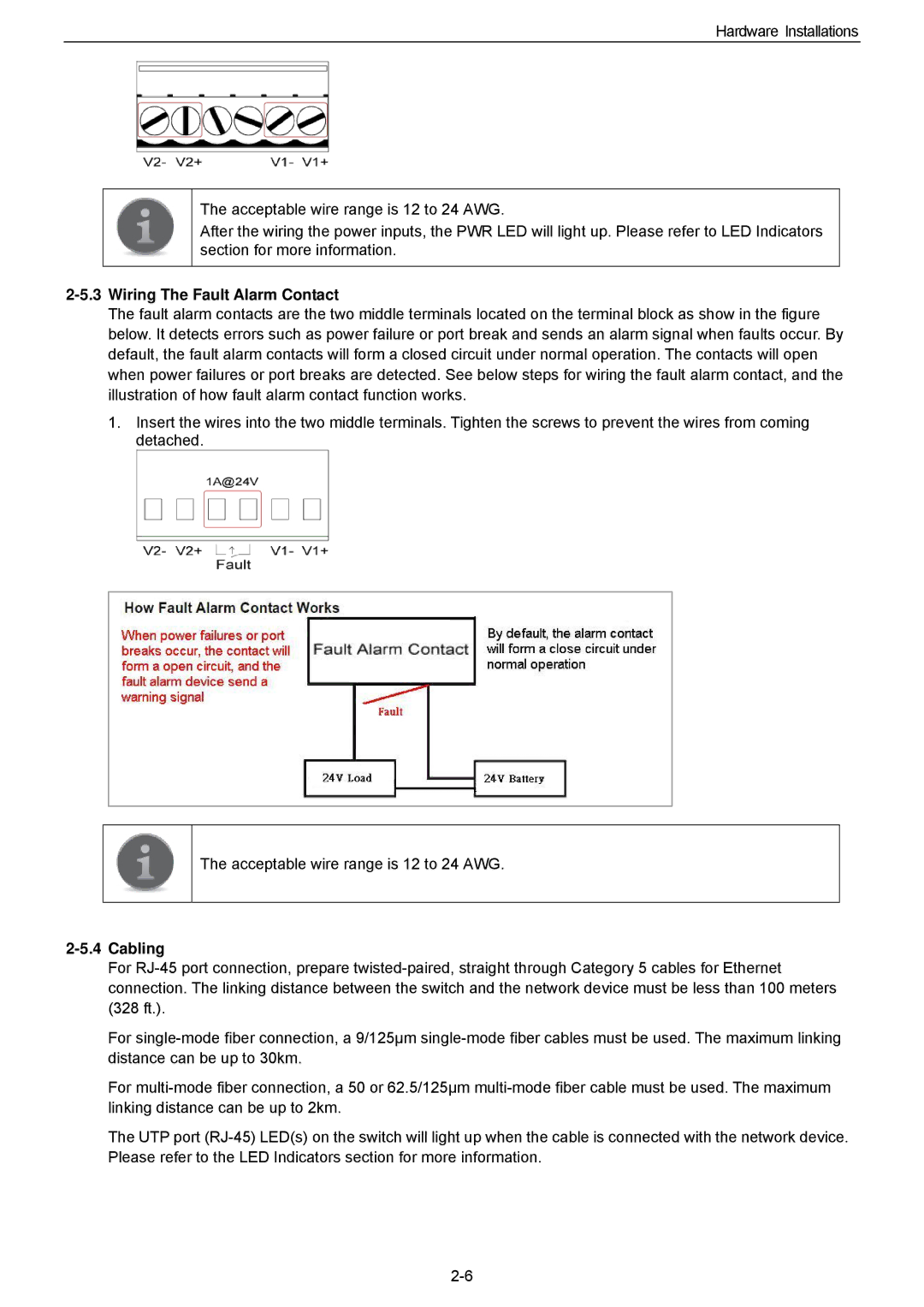
The fault alarm contacts are the two middle terminals located on the terminal block as show in the figure below. It detects errors such as power failure or port break and sends an alarm signal when faults occur. By default, the fault alarm contacts will form a closed circuit under normal operation. The contacts will open when power failures or port breaks are detected. See below steps for wiring the fault alarm contact, and the illustration of how fault alarm contact function works.

1.Insert the wires into the two middle terminals. Tighten the screws to prevent the wires from coming detached.

The acceptable wire range is 12 to 24 AWG.

2-5.4 Cabling

For RJ-45 port connection, prepare twisted-paired, straight through Category 5 cables for Ethernet connection. The linking distance between the switch and the network device must be less than 100 meters (328 ft.).

For single-mode fiber connection, a 9/125µm single-mode fiber cables must be used. The maximum linking distance can be up to 30km.

For multi-mode fiber connection, a 50 or 62.5/125µm multi-mode fiber cable must be used. The maximum linking distance can be up to 2km.

The UTP port (RJ-45) LED(s) on the switch will light up when the cable is connected with the network device. Please refer to the LED Indicators section for more information.

2-6

Page 13
Image 13
Husky HME-423E, HME-421E user manual Wiring The Fault Alarm Contact, Cabling