Chapter 5. Using the Media
The IBM TotalStorage LTO Ultrium 2 Tape Drive uses the following cartridge types:
vIBM TotalStorage LTO Ultrium 200 GB Data Cartridge (Generation 2)
vIBM LTO Ultrium Cleaning Cartridge
vIBM TotalStorage Cleaning Cartridge (Ultrium LTO 2)
The Ultrium 2 Tape Drive (Generation 2) is compatible with the cartridges of its predecessor, the IBM Ultrium Internal Tape Drive (Generation 1). Cartridge compatibility for the Ultrium 2 Tape Drive is as follows:
vReads and writes Generation 2 cartridges to Generation 2 format
vReads and writes Generation 1 cartridges to Generation 1 format
vDoes not write Generation 2 cartridges to Generation 1 format
vDoes not write Generation 1 cartridges to Generation 2 format
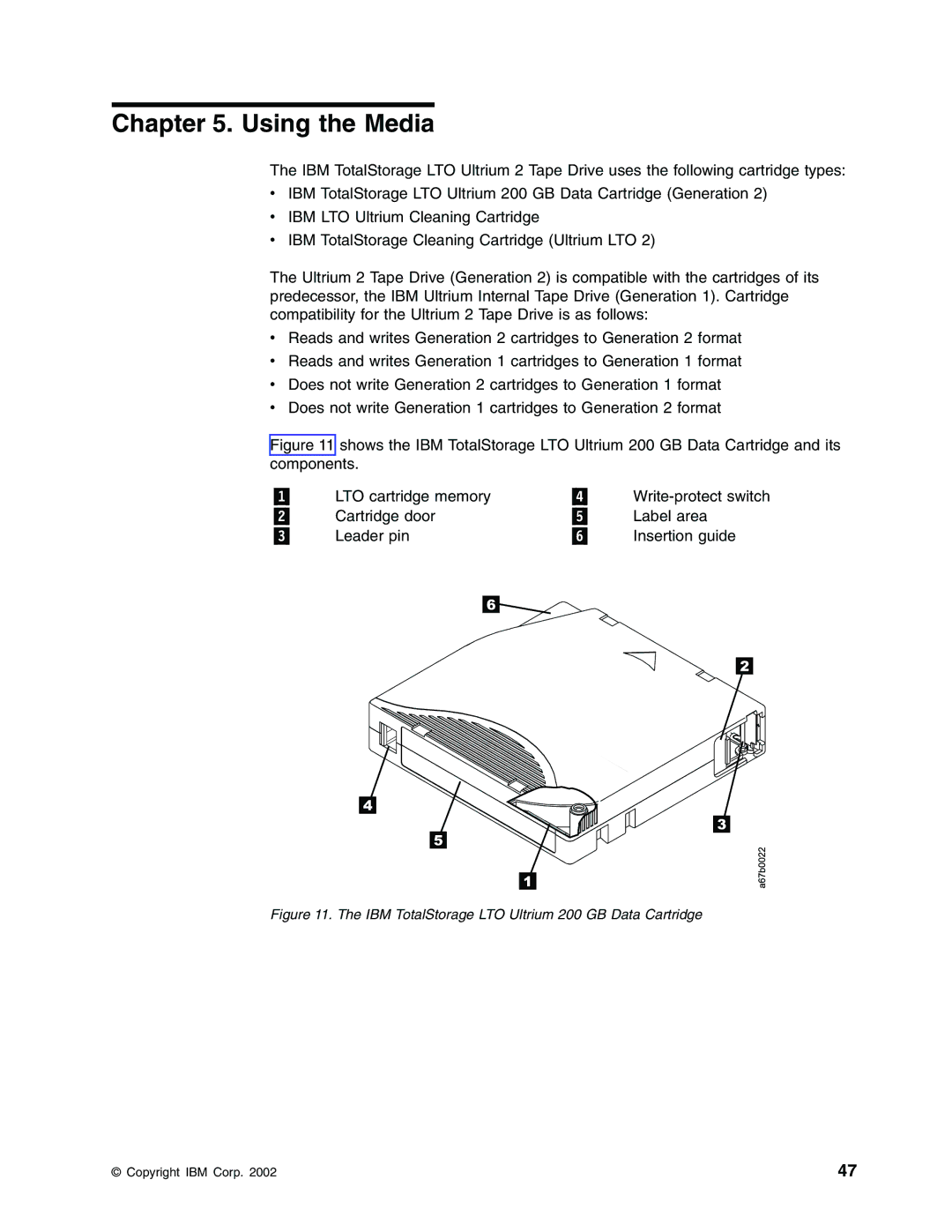
Figure 11 shows the IBM TotalStorage LTO Ultrium 200 GB Data Cartridge and its components.
LTO cartridge memory |
|
| ||||||||||||
Cartridge door |
| Label area | ||||||||||||
Leader pin |
| Insertion guide | ||||||||||||
|
|
|
|
|
|
|
|
|
|
|
|
|
|
|
|
|
|
|
|
|
|
|
|
|
|
|
|
|
|
|
|
|
|
|
|
|
|
|
|
|
|
|
|
|
|
|
|
|
|
|
|
|
|
|
|
|
|
|
|
|
|
|
|
|
|
|
|
|
|
|
|
|
|
|
|
|
|
|
|
|
|
|
|
|
|
|
|
|
|
|
|
|
|
|
|
|
|
|
|
|
|
|
|
|
|
|
|
|
|
|
|
|
|
|
|
|
|
|
|
|
|
|
|
|
|
|
|
|
|
|
|
|
|
|
|
|
|
|
|
|
|
|
|
|
|
|
|
|
|
|
|
|
|
|
|
|
|
|
|
|
|
|
|
|
|
|
|
|
|
|
|
|
|
|
|
|
|
|
|
|
|
|
|
|
|
|
|
|
|
|
|
|
|
|
|
|
|
|
|
|
|
|
|
|
|
|
|
|
|
Figure 11. The IBM TotalStorage LTO Ultrium 200 GB Data Cartridge
© Copyright IBM Corp. 2002 | 47 |