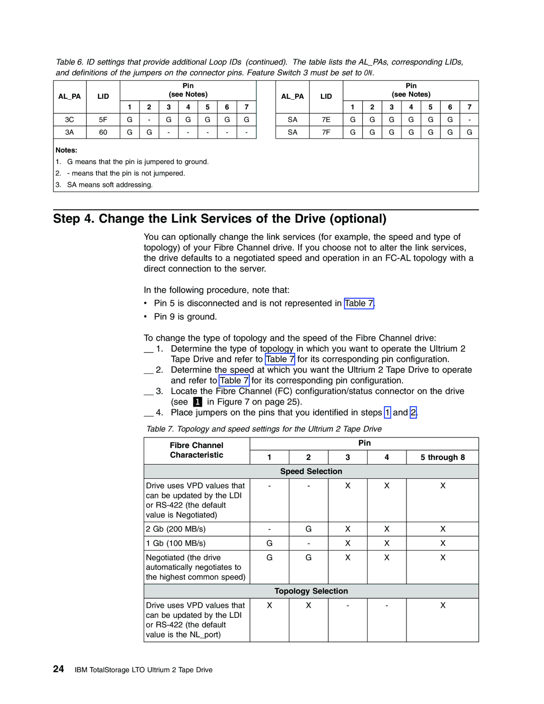
Table 6. ID settings that provide additional Loop IDs (continued). The table lists the AL_PAs, corresponding LIDs, and definitions of the jumpers on the connector pins. Feature Switch 3 must be set to ON.
|
|
|
|
|
| Pin |
|
|
|
|
|
|
|
|
| Pin |
|
|
|
AL_PA | LID |
|
| (see Notes) |
|
|
| AL_PA | LID |
|
| (see Notes) |
|
| |||||
|
|
| 1 | 2 | 3 | 4 | 5 | 6 | 7 |
|
|
| 1 | 2 | 3 | 4 | 5 | 6 | 7 |
|
|
|
|
|
|
|
|
|
|
|
|
|
|
|
|
|
|
|
|
| 3C | 5F | G | - | G | G | G | G | G |
| SA | 7E | G | G | G | G | G | G | - |
|
|
|
|
|
|
|
|
|
|
|
|
|
|
|
|
|
|
|
|
| 3A | 60 | G | G | - | - | - | - | - |
| SA | 7F | G | G | G | G | G | G | G |
|
|
|
|
|
|
|
|
|
|
|
|
|
|
|
|
|
|
| |
Notes: |
|
|
|
|
|
|
|
|
|
|
|
|
|
|
|
|
|
| |
1. | G means that the pin is jumpered to ground. |
|
|
|
|
|
|
|
|
|
|
|
| ||||||
2. | - means that the pin is not jumpered. |
|
|
|
|
|
|
|
|
|
|
|
|
| |||||
3. | SA means soft addressing. |
|
|
|
|
|
|
|
|
|
|
|
|
|
|
| |||
|
|
|
|
|
|
|
|
|
|
|
|
|
|
|
|
|
|
|
|
Step 4. Change the Link Services of the Drive (optional)
You can optionally change the link services (for example, the speed and type of topology) of your Fibre Channel drive. If you choose not to alter the link services, the drive defaults to a negotiated speed and operation in an
In the following procedure, note that:
vPin 5 is disconnected and is not represented in Table 7.
vPin 9 is ground.
To change the type of topology and the speed of the Fibre Channel drive:
__ 1. Determine the type of topology in which you want to operate the Ultrium 2 Tape Drive and refer to Table 7 for its corresponding pin configuration.
__ 2. Determine the speed at which you want the Ultrium 2 Tape Drive to operate and refer to Table 7 for its corresponding pin configuration.
__ 3. Locate the Fibre Channel (FC) configuration/status connector on the drive
(see | in Figure 7 on page 25). |
|
|
|
|
| ||||
__ 4. Place jumpers on the pins that you identified in steps 1 and 2. |
| |||||||||
Table 7. Topology and speed settings for the Ultrium 2 Tape Drive |
| |||||||||
|
|
|
|
|
|
|
|
|
| |
Fibre Channel |
|
|
|
|
| Pin |
| |||
Characteristic | 1 |
| 2 |
| 3 |
| 4 |
| 5 through 8 | |
|
|
|
|
|
|
|
|
|
|
|
|
|
| Speed Selection |
|
|
|
|
| ||
Drive uses VPD values that | - |
| - |
| X |
| X |
| X | |
can be updated by the LDI |
|
|
|
|
|
|
|
|
| |
or |
|
|
|
|
|
|
|
|
| |
value is Negotiated) |
|
|
|
|
|
|
|
|
| |
|
|
|
|
|
|
|
|
|
|
|
2 Gb (200 MB/s) |
| - |
| G |
| X |
| X |
| X |
|
|
|
|
|
|
|
|
|
|
|
1 Gb (100 MB/s) |
| G |
| - |
| X |
| X |
| X |
|
|
|
|
|
|
|
|
|
| |
Negotiated (the drive | G |
| G |
| X |
| X |
| X | |
automatically negotiates to |
|
|
|
|
|
|
|
|
| |
the highest common speed) |
|
|
|
|
|
|
|
|
| |
|
|
|
|
|
|
|
|
|
| |
|
|
| Topology Selection |
|
|
|
| |||
Drive uses VPD values that | X |
| X |
| - |
| - |
| X | |
can be updated by the LDI |
|
|
|
|
|
|
|
|
| |
or |
|
|
|
|
|
|
|
|
| |
value is the NL_port) |
|
|
|
|
|
|
|
|
| |
|
|
|
|
|
|
|
|
|
|
|