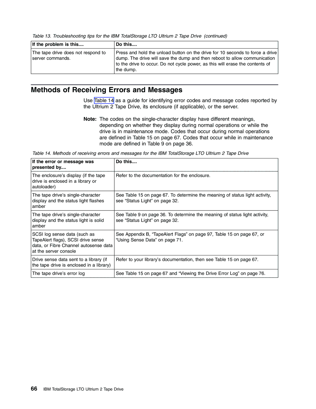
Models T400 and T400F
Setup, Operator, and Service Guide
IBM TotalStorage LTO Ultrium 2 Tape Drive
GA32-0455-00
Page
Models T400 and T400F
Setup, Operator, and Service Guide
IBM TotalStorage LTO Ultrium 2 Tape Drive
GA32-0455-00
First Edition November
Installing the Tape Drive
Contents
Specifications
Chapter
Chapter 7. Servicing the Tape Drive
Chapter 6. Resolving Problems
Chapter 4. Operating the Tape Drive
Appendix A. Tools and Supplies
Glossary Index
vi IBM TotalStorage LTO Ultrium 2 Tape Drive
Safety and Environmental Notices
Danger Notice
Caution Notice
Laser Safety and Compliance
Attention Notice
Related Publications
Preface
Intended Audience
IBM Ultrium Publications
x IBM TotalStorage LTO Ultrium 2 Tape Drive
Chapter 1. Introduction
Cartridge Compatibility
Speed Matching and Channel Calibration
Sleep Mode
Supported Operating Systems
Supported Servers and Operating Systems
Supported Servers
Supported SAN Components for Fibre Channel Attachment
SCSI Attachment
Physical Characteristics of the SCSI Interface
v Cyclic redundancy check CRC - an error-checking technique
Speed
Installing, Removing, or Resetting a Drive on an Active SCSI Bus
Address Assignments
Switched Fabric
Fibre Channel Attachment
Supported Topologies
Type of Fibre Channel Connection to Server
The Ultrium 2 Tape Drive’s Fibre Channel interface facilitates data at 2 Gb/s 200 MB/s. It automatically negotiates to a rate of 1 Gb/s 100 MB/s if the system or switch to which it connects does not support the 2-Gb rate if this is the case, you may experience performance degradation. You can force the drive to an explicit speed by placing jumpers on the Fibre Channel FC configuration/status connector. For more information, see “Step 4. Change the Link Services of the Drive optional” on page
Speed
Address Assignments
World Wide Names
Physical Characteristics of the Fibre Channel Interface
Installing, Removing, or Resetting a Drive on an Active Fibre Channel
8 IBM TotalStorage LTO Ultrium 2 Tape Drive
Supported Device Drivers
10 IBM TotalStorage LTO Ultrium 2 Tape Drive
Physical Specifications
Chapter 2. Specifications
Specification
Power Specifications
Operating
Environmental Specifications for both interface types
Environmental Factor
Storage
Chapter 3. Installing the Tape Drive
Rear View of the SCSI Drive
Feature switches SCSI connector SCSI ID connector Power connector
Library/Drive Interface LDI or RS-422 interface connector
Rear View of the Fibre Channel Drive
Chapter 3. Installing
Step 2. Remove Power from the Enclosure
Step 1. Unpack the Drive
16 IBM TotalStorage LTO Ultrium 2 Tape Drive
Setting the SCSI ID SCSI Drive Only
Setting the SCSI ID with Jumpers
Step 3. Set the SCSI ID or Arbitrated Loop Physical Address
Supplying TERMPOWER SCSI Drive Only
Setting the SCSI ID with a SCSI ID Switch
Setting the SCSI ID Through the LDI Interface
Figure 5. SCSI ID settings on the SCSI ID connector
Setting the Arbitrated Loop Physical Address Fibre Channel Drive Only
Setting the Loop ID to Provide Status About the Loop
use soft
Setting the Loop ID to Provide Additional Loop IDs
ALPA
Step 4. Change the Link Services of the Drive optional
4. Place jumpers on the pins that you identified in steps 1 and
in Figure 7 on page
Characteristic
Fibre Channel
5 through
Step 5. Mount the Tape Drive into the Enclosure
Step 6. Connect and Test Power to the Tape Drive
Step 7. Connect the Internal SCSI or Fibre Channel Cable
Step 8. Connect the Internal LDI Cable optional
Step 9. Run Drive Diagnostics
Step 10. Install the Device Drivers
Connect the External SCSI Interface to the Server
Step 13. Configure the Tape Drive to the Server, Switch, or Hub
Connect the External Fibre Channel Interface to the Server
Step 12. Connect the External LDI Interface to the Server optional
30 IBM TotalStorage LTO Ultrium 2 Tape Drive
Chapter 4. Operating the Tape Drive
Status light Unload button Single-character display Single red dot
Figure 9. Front view of the IBM TotalStorage LTO Ultrium 2 Tape Drive
The tape drive is powered on and is idle
Status Light
The tape drive has no power or is powered off
cartridge during the power-on cycle. In this case, the drive
Single Red Dot
Unload Button
Single-Character Display
Chapter 4. Operating
Inserting a Tape Cartridge
Figure 10. Inserting a cartridge into the Ultrium 2 Tape Drive
Cleaning the Drive Head
Removing a Tape Cartridge
Selecting a Diagnostic or Maintenance Function
Function Code 1 - Run SCSI or Fibre Channel Tape Drive Diagnostics
Table 9. Diagnostic and maintenance functions continued
Function Code 2 - Update Tape Drive Firmware from FMR Tape
Function Code 3 - Create FMR Tape
Function Code 5 - Copy the Drive Dump to Tape at Beginning of Tape
Table 9. Diagnostic and maintenance functions continued
Function Code 4 - Force a Drive Dump
38 IBM TotalStorage LTO Ultrium 2 Tape Drive
Table 9. Diagnostic and maintenance functions continued
Function Code 6 - Run SCSI or Fibre Channel Wrap Test
Running a SCSI Wrap Test
Testing the Circuitry at the Fiber Cable
Table 9. Diagnostic and maintenance functions continued
Testing the Circuitry at the Drive’s Fibre Channel Connector
Running a Fibre Channel Wrap Test
Table 9. Diagnostic and maintenance functions continued
Function Code 7 - Run LDI or RS-422 Wrap Test
Function Code 8 - Convert FMR Tape to Scratch Tape
Function Code A - Clear Error Code Log
Table 9. Diagnostic and maintenance functions continued
Function Code 9 - Display Error Code Log
Function Code C - Insert Cartridge into Tape Drive
Table 9. Diagnostic and maintenance functions continued
Function Code E - Test Cartridge & Media
Function Code F - Fast Read/Write Test
Function Code H - Test Head
Table 9. Diagnostic and maintenance functions continued
Function Code P or U - Enable or Disable Post Error Reporting
Function Code L - Reserved for Future Use
Updating Firmware through the SCSI or Fibre Channel Interface
Exiting Maintenance Mode
Updating the Firmware
Updating Firmware through the Library/Drive Interface
Updating the Firmware with an FMR Tape Cartridge
46 IBM TotalStorage LTO Ultrium 2 Tape Drive
Chapter 5. Using the Media
Figure 11. The IBM TotalStorage LTO Ultrium 200 GB Data Cartridge
Data Cartridge
Cleaning Cartridges
Chapter 5. Using the Media
Setting the Write-Protect Switch
Handling the Cartridges
Provide Training
Ensure Proper Packaging
Provide Proper Acclimation and Environmental Conditions
Perform a Thorough Inspection
Handle the Cartridge Carefully
Examples of Cartridge Problems
Example Improper Placement of Leader Pin
Example Split Cartridge Case
Repositioning or Reattaching a Leader Pin
Repositioning a Leader Pin
Figure 18. Rewinding the tape into the cartridge
56 IBM TotalStorage LTO Ultrium 2 Tape Drive
Cartridge manual rewind tool see
Reattaching a Leader Pin
Leader pin attach tool see
Pin supplies see
The following procedure describes how to reattach a leader pin
counterclockwise to bring the tape edge toward the cartridge door
Place a new C-clip into the retention groove
13. Use your fingers to remove the leader pin from the cavity
Environmental and Shipping Specifications for Tape Cartridges
IBM Part Number
Disposing of Tape Cartridges
Ordering Media Supplies
Product Description
In America
Ordering Custom Bar Code Labels
Table 12. Authorized suppliers of custom bar code labels
In Europe and Asia
Chapter 6. Resolving Problems
If the problem is this
Do this
Methods of Receiving Errors and Messages
66 IBM TotalStorage LTO Ultrium 2 Tape Drive
Descriptions and Corrective Actions for Errors and Messages
Code
Cause and Action
Code
Cause and Action
68 IBM TotalStorage LTO Ultrium 2 Tape Drive
Code
For Problems with Writing Data
For Problems with Reading Data
Cause and Action
For SCSI drive
Code
Cause and Action
For Fibre Channel drive
Using Sense Data
Obtaining Error Information from the RS/6000 or pSeries
rmt2
Example of a Drive Error Log
Figure 26. Example of an AIX ERRPT Drive Error Log
tape
Example of a SCSI Bus Error
Figure 27. Example of an error that suggests a SCSI bus problem
Using the Drive to Obtain a Dump
Using a Device Driver Utility to Obtain a Dump
Obtaining a Drive Dump
Viewing the Drive Error Log
Fixing a Consistent Error with a Single Drive on a SCSI Bus
Resolving Problems Reported by the Server
Fixing SCSI Bus Errors
Fixing a Consistent Error with Multiple Drives on a SCSI Bus
Fixing an Intermittent Error with a Single Drive on a SCSI Bus
Fixing an Intermittent Error with Multiples Drives on a SCSI Bus
78 IBM TotalStorage LTO Ultrium 2 Tape Drive
Fixing Fibre Channel Errors
Starting Problem Determination
Fixing a Consistent Error with a Single Drive on a Fibre Channel Loop
Fixing a Consistent Error in a Point-to-Point Topology
80 IBM TotalStorage LTO Ultrium 2 Tape Drive
Fixing Intermittent Fibre Channel Errors
Resolving Media-Related Problems
Chapter 7. Servicing the Tape Drive
Removing a SCSI Tape Drive from an Enclosure
Removing a Fibre Channel Tape Drive from an Enclosure
84 IBM TotalStorage LTO Ultrium 2 Tape Drive
Manually Removing a Tape Cartridge
Removing the Cartridge
Figure 30. Determining whether the tape is broken
86 IBM TotalStorage LTO Ultrium 2 Tape Drive
the loader motor gear
This procedure must be performed only by trained service personnel
Fixing an Internal Jam
4. Examine the drive to determine the cause of the problem
Figure 32. Rewinding the leader pin into the tape cartridge
90 IBM TotalStorage LTO Ultrium 2 Tape Drive
10. Manually rotate the loader motor gear see
92 IBM TotalStorage LTO Ultrium 2 Tape Drive
retracts and occupies the opening to the drive see
in Figure
17. Reassemble the tape drive by reversing the preceding steps
Appendix A. Tools and Supplies
IBM Part Number
Product Description
96 IBM TotalStorage LTO Ultrium 2 Tape Drive
Flag
Appendix B. TapeAlert Flags
TapeAlert Flags Supported by the Drive
Flag
Flag
Flag
Flag
Description
Flag
Flag
Flag
Description
100 IBM TotalStorage LTO Ultrium 2 Tape Drive
Notices
Trademarks
IBM TotalStorage LTO Ultrium 2 Tape Drive Models T400 and T400F
Electronic Emission Notices
Special Considerations for Electromagnetic Compatibility
Federal Communications Commission FCC Class B Statement
Japan VCCI Class B ITE Electronic Emission Statement
European Union EU Electromagnetic Compatibility Directive
Germany Electromagnetic Compatibility Directive
Notices
Warranty
Getting Help
The warranty for this product is negotiated on a per-customer basis
A. See ampere
Numbers and Symbols
Glossary
adapter. See adapter card
cartridge memory. See LTO cartridge memory
C. See Celsius
cartridge. See tape cartridge
data compression. See compression
duplex. See duplex transmission
Fibre Channel configuration/status connector
drive sense data. See SCSI drive sense data dump. See drive dump
e-mail. See electronic mail
FMR tape. See field microcode replacement tape
Gb. See gigabit GB. See gigabyte
head. See drive head
LAN. See local area network LDI. See Library/Drive Interface
LID/status connector. See loop identifier LID/status connector
I/O. See input/output
LED. See light-emitting diode
LTO. See Linear Tape-Open
log sense data. See SCSI log sense data
loop ID. See loop identifier
LTO-CM. See LTO cartridge memory LTO-DC. See LTO Data Compression
native sustained data transfer rate. See data
transfer rate
SCSI. See Small Computer Systems Interface
SC. See subscription channel connector
s. See second SAN. See Storage Area Network
SCSI interface. See Small Computer Systems Interface
second. One sixtieth of a minute
TotalStorage LTO Ultrium 2 Tape Drive
tape drive. See IBM TotalStorage LTO Ultrium 2 Tape Drive
TotalStorage LTO Ultrium 2 Tape Drive. See IBM
transfer rate. See data transfer rate
WAN. See wide area network
web. See World Wide Web
116 IBM TotalStorage LTO Ultrium 2 Tape Drive
Index A
continued
reported to enclosure
Fibre Channel connector
obtaining from RS/6000 or pSeries servers
assigning an address
Page
continued
continued
Page
122 IBM TotalStorage LTO Ultrium 2 Tape Drive
Page
GA32-0455-00