7529_eng.fm Page 52 Wednesday, November 12, 2003 8:57 AM
The base plate or transducer, depending on model, should be mounted onto a rigid surface. See Figure 1 for bolt hole pattern. Place the bolt assembly just completed into the shroud and then onto the transducer or base plate. The last step is to apply the steel washer onto the bolt before applying the nut.
IMPORTANT - Grease the threads and fit the nut.
- Ensure that the threads are kept clean and lubricated.
The joint is now ready for use. Eventually the bolt and nut threads will wear and will need to be replaced. IR recommends replacing worn joints with the appropriate bolt kit that matches your joint kit model:
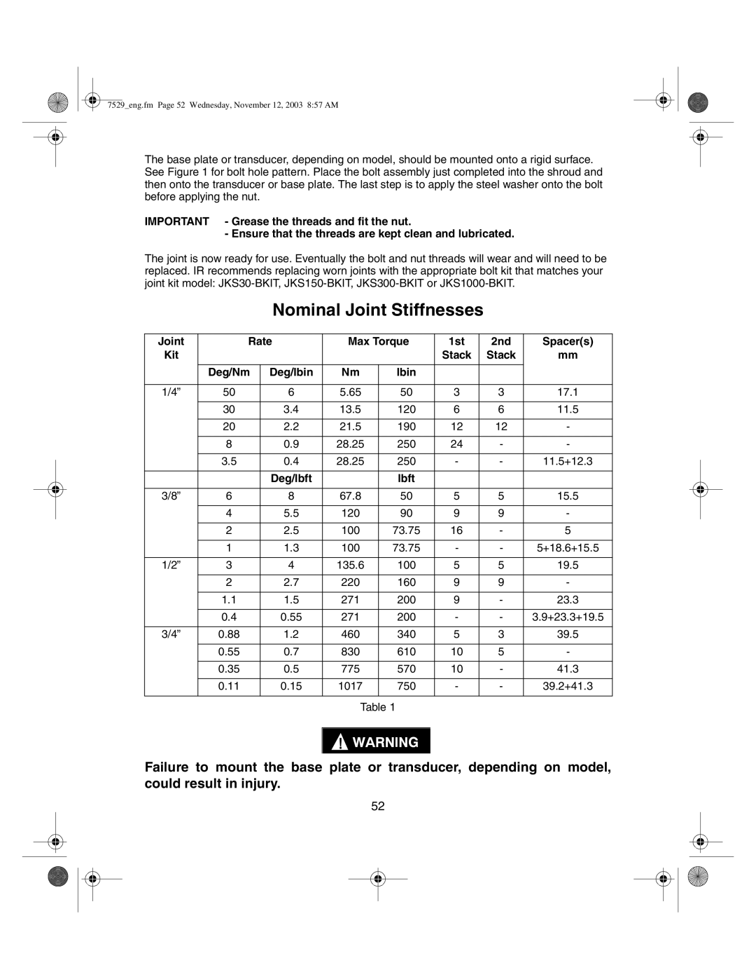
Nominal Joint Stiffnesses
Joint | Rate | Max Torque | 1st | 2nd | Spacer(s) | ||
Kit |
|
|
|
| Stack | Stack | mm |
|
|
|
|
|
|
|
|
| Deg/Nm | Deg/lbin | Nm | lbin |
|
|
|
|
|
|
|
|
|
|
|
1/4” | 50 | 6 | 5.65 | 50 | 3 | 3 | 17.1 |
|
|
|
|
|
|
|
|
| 30 | 3.4 | 13.5 | 120 | 6 | 6 | 11.5 |
|
|
|
|
|
|
|
|
| 20 | 2.2 | 21.5 | 190 | 12 | 12 | - |
|
|
|
|
|
|
|
|
| 8 | 0.9 | 28.25 | 250 | 24 | - | - |
|
|
|
|
|
|
|
|
| 3.5 | 0.4 | 28.25 | 250 | - | - | 11.5+12.3 |
|
|
|
|
|
|
|
|
|
| Deg/lbft |
| lbft |
|
|
|
|
|
|
|
|
|
|
|
3/8” | 6 | 8 | 67.8 | 50 | 5 | 5 | 15.5 |
|
|
|
|
|
|
|
|
| 4 | 5.5 | 120 | 90 | 9 | 9 | - |
|
|
|
|
|
|
|
|
| 2 | 2.5 | 100 | 73.75 | 16 | - | 5 |
|
|
|
|
|
|
|
|
| 1 | 1.3 | 100 | 73.75 | - | - | 5+18.6+15.5 |
|
|
|
|
|
|
|
|
1/2” | 3 | 4 | 135.6 | 100 | 5 | 5 | 19.5 |
|
|
|
|
|
|
|
|
| 2 | 2.7 | 220 | 160 | 9 | 9 | - |
|
|
|
|
|
|
|
|
| 1.1 | 1.5 | 271 | 200 | 9 | - | 23.3 |
|
|
|
|
|
|
|
|
| 0.4 | 0.55 | 271 | 200 | - | - | 3.9+23.3+19.5 |
|
|
|
|
|
|
|
|
3/4” | 0.88 | 1.2 | 460 | 340 | 5 | 3 | 39.5 |
|
|
|
|
|
|
|
|
| 0.55 | 0.7 | 830 | 610 | 10 | 5 | - |
|
|
|
|
|
|
|
|
| 0.35 | 0.5 | 775 | 570 | 10 | - | 41.3 |
|
|
|
|
|
|
|
|
| 0.11 | 0.15 | 1017 | 750 | - | - | 39.2+41.3 |
|
|
|
|
|
|
|
|
Table 1
Failure to mount the base plate or transducer, depending on model, could result in injury.
52