Intel® 6321ESB
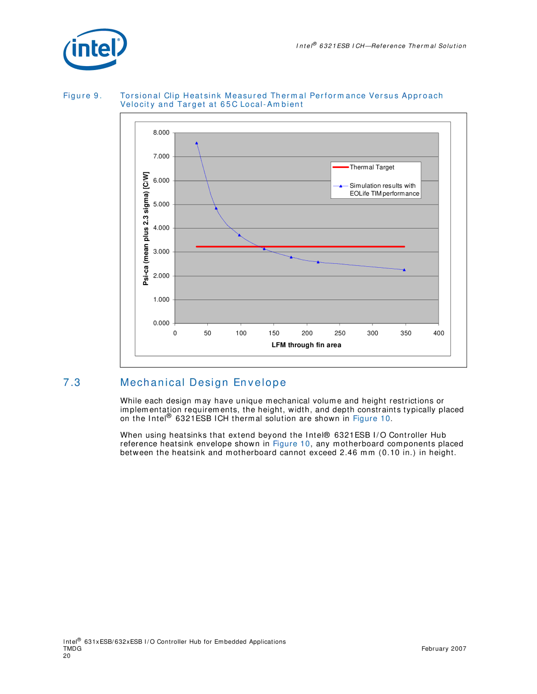
Figure 9. Torsional Clip Heatsink Measured Thermal Performance Versus Approach Velocity and Target at 65C Local-Ambient
| 8.000 |
|
|
|
|
|
|
|
|
| 7.000 |
|
|
|
|
|
|
|
|
[C/W] |
|
|
|
|
|
| Thermal Target |
|
|
6.000 |
|
|
|
|
| Simulation results with |
| ||
|
|
|
|
|
|
| |||
2.3 sigma) |
|
|
|
|
|
| EOLife TIM performance |
| |
5.000 |
|
|
|
|
|
|
|
| |
4.000 |
|
|
|
|
|
|
|
| |
plus |
|
|
|
|
|
|
|
| |
|
|
|
|
|
|
|
|
| |
3.000 |
|
|
|
|
|
|
|
| |
2.000 |
|
|
|
|
|
|
|
| |
Psi |
|
|
|
|
|
|
|
| |
|
|
|
|
|
|
|
|
| |
| 1.000 |
|
|
|
|
|
|
|
|
| 0.000 |
|
|
|
|
|
|
|
|
| 0 | 50 | 100 | 150 | 200 | 250 | 300 | 350 | 400 |
LFM through fin area
7.3Mechanical Design Envelope
While each design may have unique mechanical volume and height restrictions or implementation requirements, the height, width, and depth constraints typically placed on the Intel® 6321ESB ICH thermal solution are shown in Figure 10.
When using heatsinks that extend beyond the Intel® 6321ESB I/O Controller Hub reference heatsink envelope shown in Figure 10, any motherboard components placed between the heatsink and motherboard cannot exceed 2.46 mm (0.10 in.) in height.
Intel® 631xESB/632xESB I/O Controller Hub for Embedded Applications
TMDGFebruary 2007 20