Component Names & Functions
Rear Panel
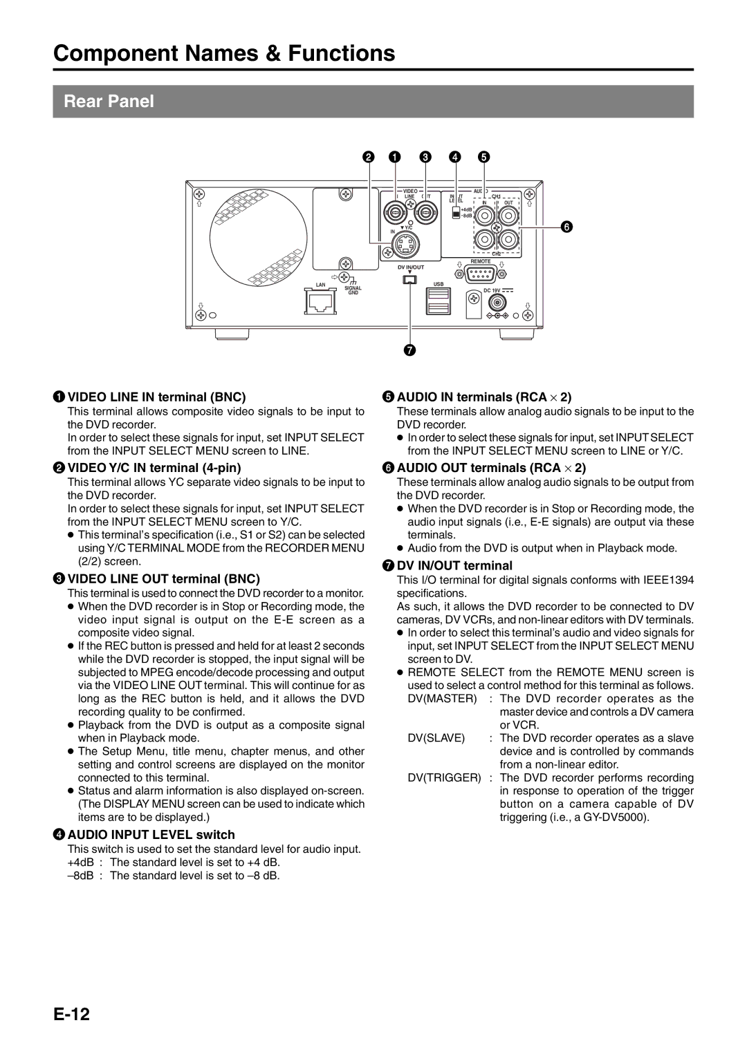
| 2 | 1 | 3 | 4 | 5 |
|
|
|
| VIDEO |
| AUDIO |
|
|
| IN | LINE OUT | INPUT | CH1 |
|
|
|
|
| LEVEL | IN | OUT |
|
|
|
|
| 4dB |
|
|
|
|
|
| 8dB |
|
|
| IN | Y/C |
|
| 6 |
|
|
|
|
|
| |
|
|
|
|
| CH2 |
|
|
| DV IN/OUT |
| REMOTE |
| |
|
|
|
|
| ||
LAN | SIGNAL |
|
| USB | DC 19V |
|
|
|
|
|
| ||
| GND |
|
|
|
| |
|
|
|
|
|
| |
1VIDEO LINE IN terminal (BNC)
This terminal allows composite video signals to be input to the DVD recorder.
In order to select these signals for input, set INPUT SELECT from the INPUT SELECT MENU screen to LINE.
7
5AUDIO IN terminals (RCA ⋅ 2)
These terminals allow analog audio signals to be input to the DVD recorder.
●In order to select these signals for input, set INPUT SELECT from the INPUT SELECT MENU screen to LINE or Y/C.
2VIDEO Y/C IN terminal (4-pin)
This terminal allows YC separate video signals to be input to the DVD recorder.
In order to select these signals for input, set INPUT SELECT from the INPUT SELECT MENU screen to Y/C.
●This terminal’s specification (i.e., S1 or S2) can be selected using Y/C TERMINAL MODE from the RECORDER MENU (2/2) screen.
3VIDEO LINE OUT terminal (BNC)
This terminal is used to connect the DVD recorder to a monitor.
●When the DVD recorder is in Stop or Recording mode, the video input signal is output on the
●If the REC button is pressed and held for at least 2 seconds while the DVD recorder is stopped, the input signal will be subjected to MPEG encode/decode processing and output via the VIDEO LINE OUT terminal. This will continue for as long as the REC button is held, and it allows the DVD recording quality to be confirmed.
●Playback from the DVD is output as a composite signal when in Playback mode.
●The Setup Menu, title menu, chapter menus, and other setting and control screens are displayed on the monitor connected to this terminal.
●Status and alarm information is also displayed
6AUDIO OUT terminals (RCA ⋅ 2)
These terminals allow analog audio signals to be output from the DVD recorder.
●When the DVD recorder is in Stop or Recording mode, the audio input signals (i.e.,
●Audio from the DVD is output when in Playback mode.
7DV IN/OUT terminal
This I/O terminal for digital signals conforms with IEEE1394 specifications.
As such, it allows the DVD recorder to be connected to DV cameras, DV VCRs, and
●In order to select this terminal’s audio and video signals for input, set INPUT SELECT from the INPUT SELECT MENU screen to DV.
●REMOTE SELECT from the REMOTE MENU screen is
used to select a control method for this terminal as follows. DV(MASTER) : The DVD recorder operates as the master device and controls a DV camera
or VCR.
DV(SLAVE) : The DVD recorder operates as a slave device and is controlled by commands from a
DV(TRIGGER) : The DVD recorder performs recording in response to operation of the trigger button on a camera capable of DV triggering (i.e., a
4AUDIO INPUT LEVEL switch
This switch is used to set the standard level for audio input. +4dB : The standard level is set to +4 dB.