Connection |
| |
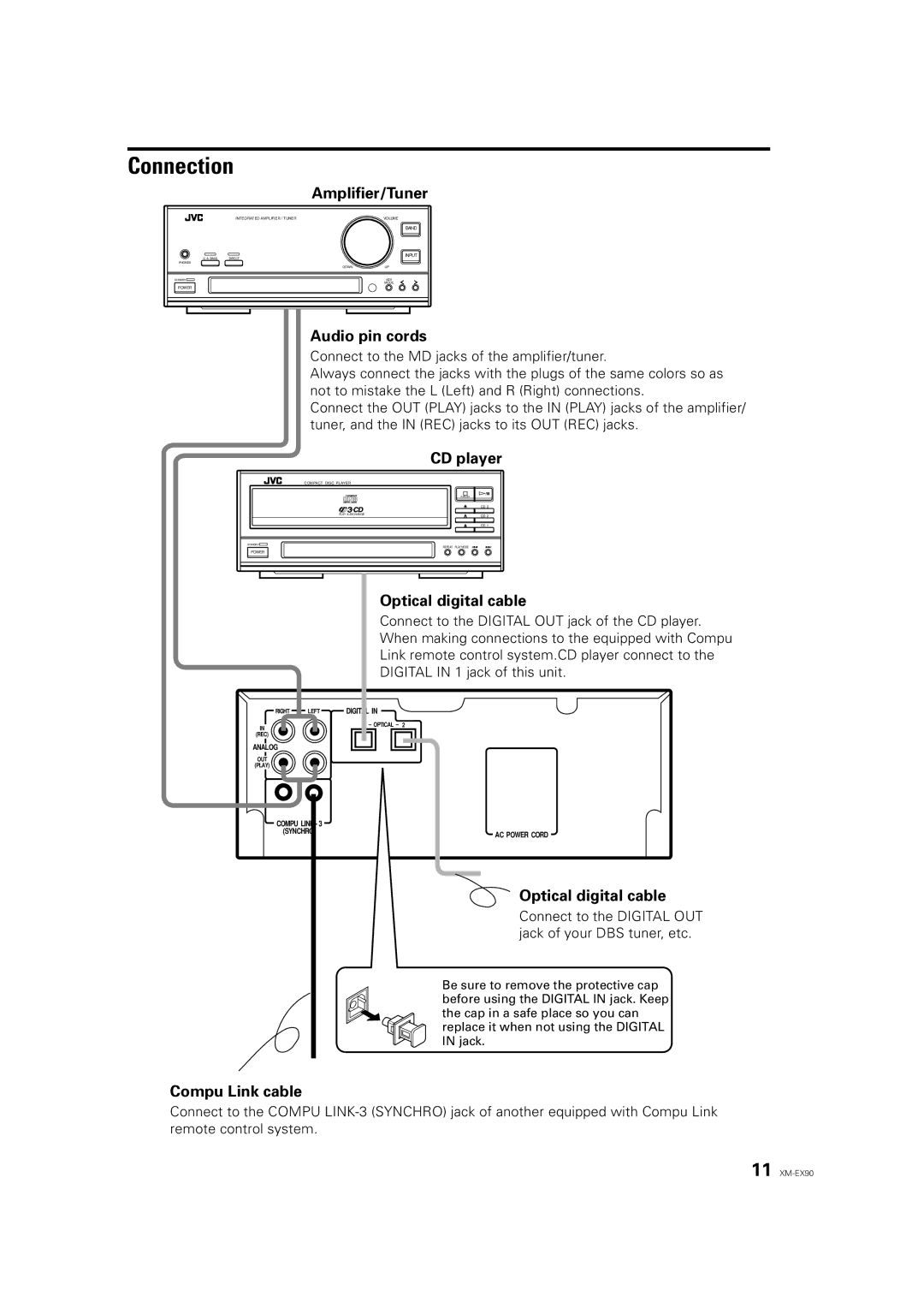
| Amplifier/Tuner | |
| INTEGRATED AMPLIFIER / TUNER | VOLUME |
|
| BAND |
S. A. BASS | DIRECT | INPUT |
| ||
PHONES |
|
|
| DOWN | UP |
STANDBY |
| KEY |
|
| MODE |
POWER |
|
|
Audio pin cords
Connect to the MD jacks of the amplifier/tuner.
Always connect the jacks with the plugs of the same colors so as not to mistake the L (Left) and R (Right) connections.
Connect the OUT (PLAY) jacks to the IN (PLAY) jacks of the amplifier/ tuner, and the IN (REC) jacks to its OUT (REC) jacks.
CD player
COMPACT DISC PLAYER |
|
| /CANCEL |
| CD 3 |
PLAY & EXCHANGE | CD 2 |
| CD 1 |
STANDBY |
|
REPEAT | PLAY MODE |
POWER |
|
Optical digital cable
Connect to the DIGITAL OUT jack of the CD player.
When making connections to the equipped with Compu
Link remote control system.CD player connect to the
DIGITAL IN 1 jack of this unit.
RIGHT | LEFT | DIGITAL IN |
IN
1 – OPTICAL – 2
(REC)
ANALOG
OUT
(PLAY)
COMPU LINK - 3
(SYNCHRO)
Compu Link cable
AC POWER CORD
![]() Optical digital cable
Optical digital cable
Connect to the DIGITAL OUT jack of your DBS tuner, etc.
Be sure to remove the protective cap before using the DIGITAL IN jack. Keep the cap in a safe place so you can replace it when not using the DIGITAL IN jack.
Connect to the COMPU
11