Section 1 Descriptions and Service Views
1.1 Introduction
The generator set specification sheets provide specific generator and engine information. Refer to the spec sheet for data not supplied in this manual. Consult the generator set service manual, engine operation manual, and engine service manual for additional specifications. Obtain copies of the latest spec sheets, manuals, diagrams, and drawings from your local distributor/ dealer.
1.2 Engine
The 8RESV generator set has a
D Efficient overhead valve design and full pressure lubrication for maximum power, torque, and reliability under all operating conditions.
DDependable,
D
D
1.3 Generator Set Enclosure
The generator set is housed in a steel enclosure which is dipped in
To open the roof, insert the tool provided with the enclosure and turn counterclockwise 1/4 turn. Then just raise the roof. The roof stays open until you are ready to close it.
Be sure to close and lock the enclosure, and keep the tool in a secure location.
1.4 Alternator
The generator uses Kohler’s unique PowerBoostt voltage regulation system, which provides instant response to load changes.
PowerBoostt ensures reliable motor starting and consistent voltage levels. PowerBoostt utilizes a voltage excitation system that employs a winding independent of the main output windings to provide excitation voltage.
1.5 Transfer Switch
The RDC2 and DC2 controllers are designed to interface with and control the Kohler Model RXT Automatic Transfer Switch (ATS). Do not use the Kohler Model RRT transfer switch with the RDC2 or DC2 controller.
If the power system uses a different model transfer switch, the RDC2 and DC2 controllers will not control the transfer switch. An ATS other than the Model RXT must be equipped with a transfer switch controller and engine start contacts that connect to the remote engine start terminals on the generator set.
1.6 Controllers
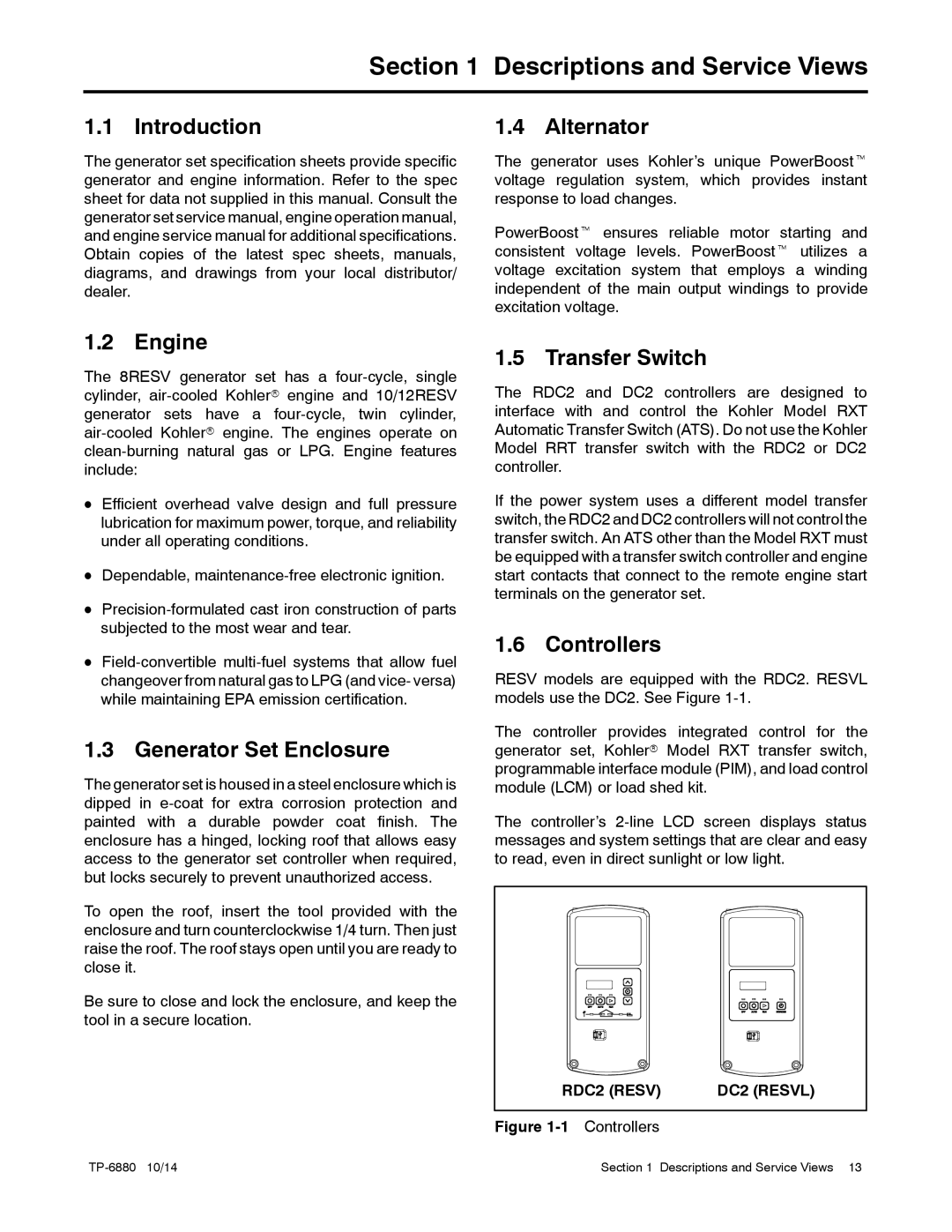
RESV models are equipped with the RDC2. RESVL models use the DC2. See Figure
The controller provides integrated control for the generator set, Kohlerr Model RXT transfer switch, programmable interface module (PIM), and load control module (LCM) or load shed kit.
The controller’s
RDC2 (RESV) | DC2 (RESVL) |
Figure |
|
Section 1 Descriptions and Service Views 13 |