XPress DR+ User Guide
Technical Support Sales Offices
Lantronix Corporate Headquarters
Date Rev Comments
Contents
Configuration Using Web Manager
Using DeviceInstaller
Contents
Setup Mode Server Configuration
Configuration Using Telnet or Serial Port Setup Mode
Setup Mode Channel Configuration
Expert Settings Option 5
Setup Mode Advanced Settings
Appendix D Binary to Hexadecimal Conversions 108
Firmware Upgrades
Monitor Mode
Troubleshooting and Technical Support
Figures
Appendix F Warranty 115 Index 116
Tables
Chapter Description
Using This Guide
Purpose and Audience
Summary of Chapters
Additional Documentation
Using This Guide
Product Description
Introduction
XPress DR+ Front
Introduction
Network Protocols Serial Tunneling
Industrial Automation Protocols
Example of Serial Tunneling
XPress DR+ Application Examples
Port Numbers
Addresses and Port Numbers
Hardware Address
IP Address
Lantronix Web Manager. See Configuration Using Web Manager
Configuration Methods
What Must the User Provide?
Installation and Hardware
Physically Connecting the XPress DR+
Whats in the Box?
XPress DR+ Front Panel
Installation and Hardware
Front of XPress DR+
Serial Interface
Serial Screw Terminal Pinout for RS485 2-Wire
Screw Terminal Serial Connectors
RJ45 Serial Connector Pinouts
Serial Screw Terminal Pinout for RS422 4-Wire
DTE, 9-Pin XPress DR+ Female Serial RJ45
Pin RS-232 to Serial RJ45 Cable P/N
Typical RJ45 Connector
Ethernet Interface Signals
Ethernet Interface
Reset Switch
Power Requirements
Multi-Drop Ethernet Connections
RXD Activity LED TXD Activity LED Ethernet Link LED
LEDs
Ethernet Activity LED
Status Meaning
Dimensions
XPress DR+ LED Functions
Product Information Label
Wall Mount Bracket
Application Examples
XPress DR+W
Serial Tunneling Network
Serial Tunneling Infrastructure
Ad Hoc Network
XPress DR+W
Ad Hoc XPress DR+W Connection
Physically Connecting the XPress DR+W
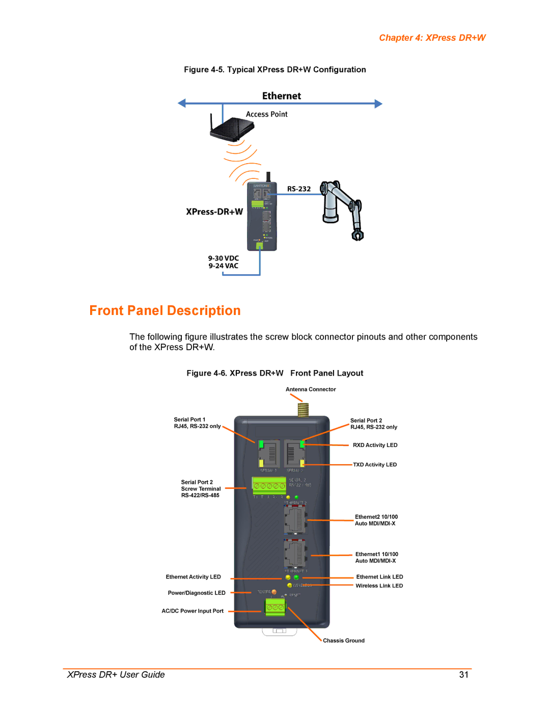
Front Panel Description
Typical XPress DR+W Configuration
XPress DR+W LED Functions
Required Information for Initial Configuration
IP Address Subnet Mask Gateway
Installing the XPress DR+W for Initial Configuration
Server Configuration Option
Wlan Settings
Options Bit
Network Mode XPress DR+W only
BootP/DHCP/AutoIP options
Set Gateway IP Address
Change Dhcp Device Name
Wlan Configuration Option
Change Telnet Configuration Password
Netmask Number of Bits for Host Part
Network Name Ssid
Topology
Adhoc Network Channel
Hex
Key Type Encryption Key
Passphrase
WPA
Fixed or Automatic Data Rate
WPA2/802.11i
Transmission Data Rate
Next Steps
Assigning an IP Address
Using DeviceInstaller
Installing DeviceInstaller
To install DeviceInstaller
To view the units current settings
Accessing the XPress DR+ Using DeviceInstaller
Viewing the Current Configuration
Using DeviceInstaller
Setting Description
Supports Dynamic IP
Supports Configurable
Pins
Supports Http Setup
Accessing XPress DR+ Using DeviceInstaller
Configuration Using Web Manager
Configuration Using Web Manager
Lantronix Web Manager
Network Configuration
Dhcp Host Name
Automatic IP Address Configuration
To assign an IP address automatically
AutoIP
To assign an IP address manually
Server Configuration
Static IP Address Configuration
Default Gateway
To configure the units device server settings
Server Configuration
Advanced
To configure the units host list
Host List Configuration
0x77FE Server Port MTU Size
To configure the channel’s serial settings
Channel Configuration
Serial Settings
Retry Settings
Channel
Port Settings
Flush Input Buffer Serial to Network
Pack Control
Flush Output Buffer Network to Serial
To configure a channel’s TCP settings
Connection Settings TCP
Connect Protocol
Connect Mode Passive Connection
Connect Mode Active Connection
Endpoint Configuration
Common Options
Connection Settings UDP
Disconnect Mode
To configure a channel’s UDP settings
Datagram Type
Datagram Mode
Device Address Table
Wlan Configuration XPress DR+W only
Wlan Settings Ad Hoc Network Type
To configure the XPress DR+W’s Wlan settings
Channel
Wireless Network Configuration
Network Name Ssid
Network Type
WEP Options
Wireless Network Security
WPA Options
WPA2/802.11i Options
Applying Settings
Applying Factory Defaults
Advanced Settings
Accessing Setup Mode
Configuration Using Telnet or Serial Port Setup Mode
Serial Port Connection
Configuration Using Telnet or Serial Port Setup Mode
To establish a Telnet connection
To exit setup mode
Exiting Setup Mode
Setup Mode Server Configuration
Setup Mode Server Configuration
Dhcp Name
Channel 1 Option 1 and Channel 2 Option
Setup Mode Channel Configuration
Baudrate
Common I/F Mode Setting Binary Hex
Interface Mode
Setup Mode Channel Configuration
Mode Option
Port Numbers Reserved for
Flow
Port Number
Flow Control Option Hex
Connect Mode Option
Connect Mode
Response
Incoming Connection
Active Startup
Connection
Autostart Automatic
Hostlist
Directed UDP
Modem Mode
To enable the hostlist
Datagram Type
Message Meaning
Modem Mode Commands
Modem Mode Function Command
Auto Increment Source Port
Send the Escape Sequence +++ in Modem Mode
Remote IP Address
DisConnMode
Disconnect Mode Option
Disconnect Mode Options
Remote Port
Pack Control
Flush Mode Buffer Flushing
Option
Send Characters
DisConnTime Inactivity Timeout
Packing Interval
Trailing Characters
Telnet Terminal Type
Channel Port Password
Wlan Settings XPress DR+W Only
Send Characters
Topology 0=Infrastructure, 1=Adhoc 0 ?
WEP
WEP64 or 13 WEP128 bytes and limits the number of key
TX Data rate 0=fixed, 1=auto fallback 1 ?
Enable Power Management
Disable Monitor Mode at bootup
Setup Mode Advanced Settings
Expert Settings Option
ARP Cache timeout in seconds
Http Port Number
Security Settings Option
Enable alternate MAC
Setup Mode Advanced Settings
Disable Port 77FE Hex
Disable Snmp
Disable Telnet Setup
Disable Tftp Firmware Upgrade
Default Settings Option
Topology AdHoc Network Name
Expert Settings
Security Settings
Wlan Settings XPress DR+W only
ROM File
Firmware Upgrades
Using Tftp Graphical User Interface
Obtaining Firmware Reloading Firmware
Firmware Upgrades
Using Tftp Command Line Interface
To recover firmware
Firmware Upgrades
Monitor Mode Commands
Monitor Mode
Entering Monitor Mode Using the Serial Port
Entering Monitor Mode Using the Network Port
G0, G1, ....,Ge, Gf
Monitor Mode
Command Command Name Function
Monitor Mode Commands
Response Meaning
Command Response Codes
Problems and Error Messages
Troubleshooting and Technical Support
Problems and Error Messages
Problem/Message Reason Solution
Troubleshooting and Technical Support
XPress DR+ User Guide 101
Technical Support Europe, Middle East, and Africa
Technical Support
XPress DR+ and XPress DR+W Specifications
Appendix a Technical Specifications
XPress DR+W Wireless Specifications
Appendix a Technical Specifications
Category Ieee 802.11b/g
Lantronix P/N Description
Appendix B Lantronix Cables and Adapters
Applications
AutoIP
Appendix C Alternative Methods of Assigning an IP Address
Appendix C Alternative Methods of Assigning an IP Address
ARP and Telnet
To assign a temporary IP address
Scientific Calculator
Appendix D Binary to Hexadecimal Conversions
Converting Binary to Hexadecimal
Conversion Table
Appendix D Binary to Hexadecimal Conversions
Emissions Immunity
Appendix E Compliance Information
Declaration of Conformity
Electromagnetic Emissions and Immunity XPress DR+
Radio
Appendix E Compliance Information
Electromagnetic Emissions and Immunity XPress DR+W
USA Federal Communications Commission FCC Notice
XPress DR+W Regulatory Information
Canada Industry Canada Notice
Antenna Notice
Europe R&TTE Directive 99/5/EC, Wireless Notice
Exposure of Humans to RF Fields
Australia & New Zealand Wireless Notice
Appendix F Warranty
Index