ThinkServer RD430 User Guide
First Edition August Copyright Lenovo
Contents
Index 199
Safety information
在使用本产品之前,请务必先阅读和了解产品附带的文档 DVD 中的多语言安全说明。
Statement
≥ 18 kg 39.7 lb ≥ 32 kg 70.5 lb ≥ 55 kg 121.2 lb
Vii
Statement Following label indicates a potential heat hazard
Copyright Lenovo
ThinkServer RD430 User Guide
General information
Introduction
Server documentation
Printed documents
Safety Information
Documentation DVD
Document only for trained service personnel
Server setup road map
ThinkServer RD430 User Guide
Product overview
Server package
Features
Security features
Input/Output I/O features
Reliability, availability, and serviceability
Basic system management features
Advanced system management features
RAID
Specifications
Dimensions
RAID configuration utilities
ThinkServer EasyUpdate Firmware Updater
Bios and TMM update utilities
Software
Locations
ThinkServer Smart Grid Technology
Machine type, model, and serial number label
Label on server models with 2.5-inch hard disk drive bays
Front view of the server
Label on server models with 12 3.5-inch hard disk drive bays
Inch hard disk drive area
Rack handle left Rack handle right
Front panel
Diagnostic panel
Pull-out information card
Slim optical drive
Front USB connectors
Power switch with power status LED
ID button with ID LED
System error LED
NIC 1 status LED NIC 2 status LED
Right cage with an EMI-protective panel
Front panel
Front panel
Power switch with power status LED
Intelligent Diagnostics Module IDM
Diagnostic module
VGA DB-15 connector
Intelligent Diagnostics Module Premium IDM Premium
System fan error LEDs
System fans
CPU1 Dimm status LEDs CPU2 Dimm status LEDs
Power supply error LEDs
Rear view of the server
Microprocessor status LEDs also known as CPU status LEDs
Hot-swap redundant power supply 2 available in some models
Following illustration shows the rear view of the server
PCI Express card area for cards on the riser card assembly
Riser card assembly
PCI Express card area for cards on the riser card assembly
USB connectors
Ethernet connectors RJ-45
Serial port
Server components
ID LED
ThinkServer RD430 User Guide
Product overview
ThinkServer RD430 User Guide
Hot-swap hard disk drive status LEDs
Inch hot-swap hard disk drive status LEDs
ThinkServer RAID 500 Adapter
RAID 5 key connector
RAID card
Port
ThinkServer RAID 700 Adapter
Board-to-board connector
Expander card
Ports
Hot-swap hard disk drive backplane
Expander card
Optical drive power connector
8-pin power connector
Mini-SAS ports
Signal cable connector
Mini-SAS ports
Connecting cables from the RAID card to the backplane
Mini-SAS to mini-SAS signal cable connections
Pin power connector
Connecting cables from the RAID card to the backplane
ThinkServer RD430 User Guide
Product overview
Connecting cables from the system board to the backplane
System board components
System board components
Diagnostic module connector
Front panel connector
Internal USB connector
Front VGA connector
TPM connector
Internal USB Type a connector
TMM Premium connector
Riser card assembly 1 slot
System fan connectors
System board jumpers and switches
Backplane power connector
Microprocessor socket
System board jumpers and switches
Clear Cmos jumper
ThinkServer RD430 User Guide
Bios recovery switch
System board switches
Clear password switch
ME in force update switch
System board LEDs
TMM status LED also known as BMC status LED
TMM status LED Color Description
ThinkServer RD430 User Guide
Turning on the server
Turning off the server
ThinkServer RD430 User Guide
Starting the Setup Utility program
Using the Setup Utility program
Viewing information in the Setup Utility program
Main menu
Setup Utility program interface
Advanced menu
Security menu
Server Management menu
Boot Manager menu
Setting the system date and time
Boot Options menu
Save & Exit menu
Password considerations
Using passwords
Setup Utility program password types
Setting, changing, or deleting a password
Configuring the TPM function
Selecting a startup device
Exiting the Setup Utility program
Setting the mode of the Ethernet connector
Updating or recovering the Bios
Updating flashing the Bios
Recovering from a Bios update failure
Using the ThinkServer EasyStartup program
Features of the ThinkServer EasyStartup program
Starting the ThinkServer EasyStartup program
Home
Configure RAID
Install operating system
Compatibility notes
Configuring RAID
About RAID
Configuring the server
RAID array status
Configuring RAID using the ThinkServer EasyStartup program
Configuring the ThinkServer RAID
Online
LSI Software RAID Configuration Utility program interface
Creating, adding, or deleting a RAID array
Objects Adapter
Setting a hot-spare drive
Initializing a virtual drive
Rebuilding a physical drive
Running a consistency check
Configuring the advanced SATA/SAS hardware RAID
Installing and using the MegaRAID Storage Manager program
Using the Firmware Updater program
Configuring the Ethernet controllers
Updating the firmware
Using the Lenovo ThinkServer EasyManage program
ThinkServer RD430 User Guide
Precautions
Guidelines
Handling static-sensitive devices
System reliability guidelines
Working inside the server with the power on
Removing the server cover
Pressing the release button
Removing and reinstalling the front bezel
Removing the server cover
Installing, removing, or replacing hardware
Removing the front bezel
Removing and reinstalling the rack handles
ThinkServer RD430 User Guide
Installing the rack handles
Go to Completing the parts replacement on
Removing and reinstalling the cooling shroud
Removing the cooling shroud
Removing and reinstalling the left cage
Removing the left cage
Installing or removing a memory module
Memory module installation rules
Memory slots on the system board
CPU1 Dimm
Installing a memory module
Opening the retaining clips of the memory slot
Removing a memory module
What to do next
Installing or removing the RAID card
Installing the RAID card
Removing a PCI Express card slot bracket
Installing the RAID card
Removing the RAID card
Removing the RAID card
Installing the TR 500 Key
Installing the TR 500 Key
Removing the TR 500 Key
Installing or removing the ThinkServer RAID 700 Battery
Removing the TR 500 Key
Installing the TR 700 Battery
Removing the TR 700 Battery
Installing the TR 700 Battery
Installing or removing the expander card
Removing the TR 700 Battery
Installing the expander card
Installing the expander card
Removing the expander card
Installing or removing an Ethernet card
Installing an Ethernet card
Removing a PCI Express card slot bracket
Removing the full-height bracket from the Ethernet card
Installing an Ethernet card
Removing an Ethernet card
Removing an Ethernet card
Installing the TR 300 Key
Installing the TR 300 Key
Removing the TR 300 Key
Installing, removing, or replacing hardware
Removing the TR 300 Key
Installing the TMM Premium
Installing the TMM Premium
Removing the TMM Premium
Removing the TMM Premium
Installing the TPM
Installing the TPM
Removing the TPM
ThinkServer RD430 User Guide
Installing or replacing a hot-swap redundant power supply
Removing the TPM
ThinkServer RD430 User Guide
Removing the protective shield for the power supply bay
Removing a hot-swap redundant power supply
Installing or replacing a heat sink
Removing the screws that secure the heat sink
Installing or replacing the microprocessor
Installing the second microprocessor
ThinkServer RD430 User Guide
Opening the small handle and microprocessor retainer
Do not touch the pins
Replacing the microprocessor
Securing the microprocessor in the socket
Opening the small handle and microprocessor retainer
Removing the microprocessor
Installing the microprocessor
Installing or replacing the optical drive
ThinkServer RD430 User Guide
Installing, removing, or replacing hardware
Installing the optical drive retaining bracket
Installing, removing, or replacing hardware
Installing or replacing a hot-swap hard disk drive
Connecting cables to the rear of the optical drive
Installing, removing, or replacing hardware
Removing the 3.5-inch hot-swap hard disk drive or dummy tray
Removing the 2.5-inch hot-swap hard disk drive or dummy tray
Installing the 2.5-inch hot-swap hard disk drive
Replacing the hot-swap hard disk drive backplane
Installing, removing, or replacing hardware
ThinkServer RD430 User Guide
What to do next
ThinkServer RD430 User Guide
What to do next
ThinkServer RD430 User Guide
Replacing the riser card assembly
Lifting the riser card assembly 1 off the chassis
Installing the riser card assembly
Lifting the riser card assembly 2 off the chassis
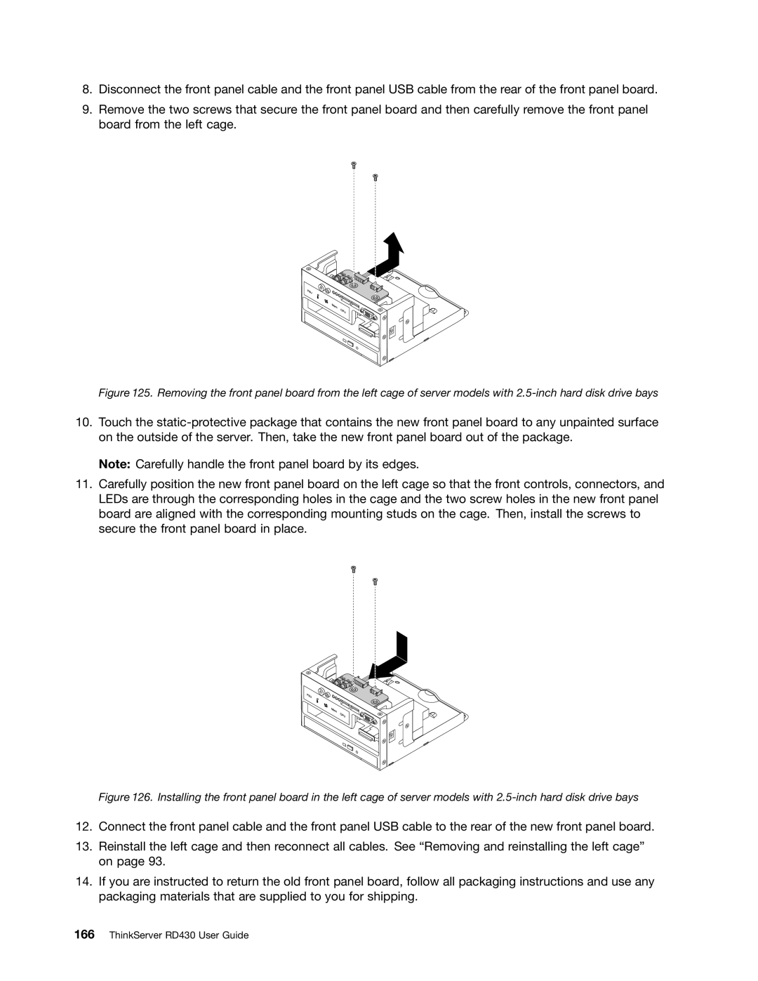
Replacing the front panel board
ThinkServer RD430 User Guide
What to do next
ThinkServer RD430 User Guide
Replacing the diagnostic module
ThinkServer RD430 User Guide
What to do next
Replacing a system fan
Removing the system fan
Replacing the system board battery
Installing the system fan
Installing, removing, or replacing hardware
Completing the parts replacement
Reinstalling the server cover and reconnecting cables
Installing, removing, or replacing hardware
Installing the server cover
Updating the server configuration
ThinkServer RD430 User Guide
Viewing the system event log
Troubleshooting procedure
Viewing the status and diagnostic LEDs
179
ThinkServer EasyStartup program problems
Basic troubleshooting tables
Optical drive problems
Hard disk drive problems
Memory module problems
Keyboard, mouse, and USB device problems
Replace the mouse or pointing device
ThinkServer Web site
Using the documentation
Information resources
Lenovo Support Web site
Calling for service
Help and service
Before you call
Using other services
Purchasing additional services
ThinkServer RD430 User Guide
Appendix A. Notices
189
Trademarks
Important notes
Battery return program
Requirement for batteries containing perchlorate
Particulate contamination
Important information for the European Directive 2002/96/EC
Appendix A. Notices
ThinkServer RD430 User Guide
Appendix A. Notices
Electronic emission notices
German Ordinance for Work gloss statement
Export classification notice
Federal Communications Commission FCC Statement
Appendix A. Notices
Energy Star model information
Index
199
TPM
201
RAID
LED TPM
203
ThinkServer RD430 User Guide