5 ![]()
![]() 8
8 ![]()
![]() 9
9
Ethernet connectors (RJ-45)
Used to attach an Ethernet cable for a LAN. Each Ethernet connector has two status LEDs to help you identify the Ethernet connectivity, activity, and connection speed.
Notes:
•The Ethernet connector 0 (callout 9 ) marked with “MGMT” is for system management. If you want to use remote management functions, you need to connect an Ethernet cable to the Ethernet connector 0.
•The Ethernet connector 0 for system management is 82574L by default. If you have selected share mode for the 82574L Ethernet connector in the Setup Utility program, you can use the connector as an ordinary Ethernet connector with 100 Mbps network connectivity. However, teaming with other Ethernet connectors is not supported if the management Ethernet connector is used as an ordinary Ethernet connector. For detailed information about setting the mode of the Ethernet connector for system management, see “Setting the mode of the Ethernet connector 0” on page 65.
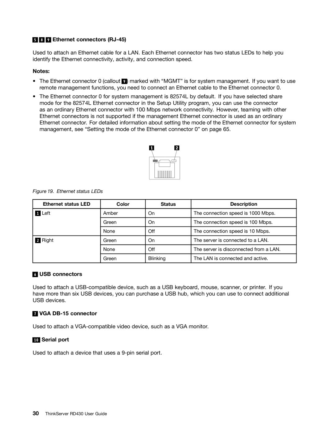
Figure 19. Ethernet status LEDs
|
| Ethernet status LED | Color | Status | Description |
|
|
|
|
|
|
|
| Left | Amber | On | The connection speed is 1000 Mbps. |
| 1 | ||||
|
|
|
|
|
|
|
|
| Green | On | The connection speed is 100 Mbps. |
|
|
|
|
|
|
|
|
| None | Off | The connection speed is 10 Mbps. |
|
|
|
|
| |
| Right | Green | On | The server is connected to a LAN. | |
| 2 | ||||
|
|
|
|
|
|
|
|
| None | Off | The server is disconnected from a LAN. |
|
|
|
|
|
|
|
|
| Green | Blinking | The LAN is connected and active. |
|
|
|
|
|
|
6
USB connectors
Used to attach a
7
VGA DB-15 connector
Used to attach a
10
Serial port
Used to attach a device that uses a