Front view of server models with
The following illustration shows the front view of server models with
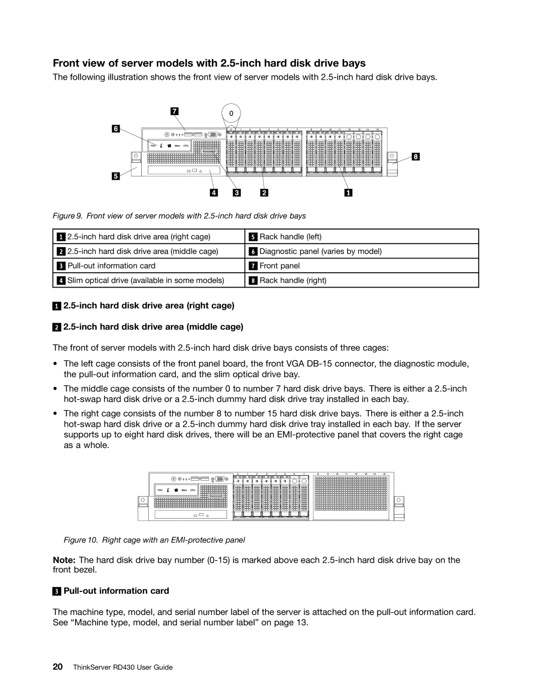
Figure 9. Front view of server models with 2.5-inch hard disk drive bays
|
|
|
| Rack handle (left) | |
| 1 |
| 5 | ||
|
|
|
|
|
|
|
|
|
| Diagnostic panel (varies by model) | |
| 2 | 6 | |||
|
|
|
|
|
|
|
|
|
| Front panel | |
| 3 | 7 | |||
|
|
|
|
|
|
|
| Slim optical drive (available in some models) |
|
| Rack handle (right) |
| 4 | 8 | |||
|
|
|
|
|
|
1
2
The front of server models with
•The left cage consists of the front panel board, the front VGA
•The middle cage consists of the number 0 to number 7 hard disk drive bays. There is either a
•The right cage consists of the number 8 to number 15 hard disk drive bays. There is either a
Figure 10. Right cage with an EMI-protective panel
Note: The hard disk drive bay number
3
Pull-out information card
The machine type, model, and serial number label of the server is attached on the