Return to Master TOC
Return to Master TOC
Section | Section |
TABLE OF CONTENTS
-THEORY OF OPERATION SECTION-
Theory of Operation | Section E |
General Description | |
Input Line Voltage and Auxiliary Transformer | |
Precharge and Protection | |
Main Transformer | |
Output Section and Torch | |
Control Board | |
Protection Circuits | |
Overload Protection | |
Thermal Protection | |
Accidental Operation Protection | |
Safety | |
Insulated Gate Bipolar Transistor (IGBT) Operation |
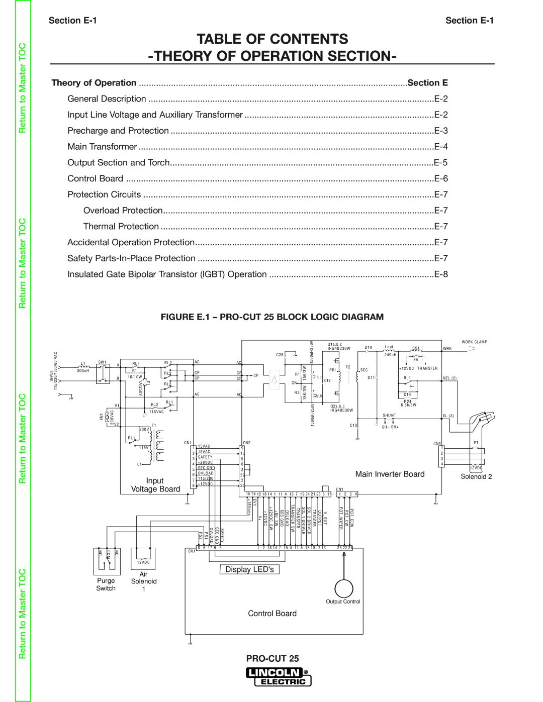
FIGURE E.1 – PRO-CUT 25 BLOCK LOGIC DIAGRAM
INPUT 115/230/1/50/60 VAC
L1 SW1 A 300uH
B |
RL3 |
| RL2 |
R1 |
| RL2 |
10/10W |
| |
F1 |
| |
1A/250V | RL2 |
C26
AC | AC |
| |
CP | CP | CP | |
CP | CP | ||
| |||
AC | AC |
|
R1 ![]()
![]()
CP
R2 ![]()
![]()
15K/3W 15K/3W
1500uF/250V
+
C1a,b
+
C2a,b
Q1a,b,c | D10 | Lout | BS1 |
|
IRG4BC30W | WRK | |||
|
| 240uH | 8A |
|
|
|
|
| |
T2 | SEC |
| +12VDC TRANSFER |
|
PRI |
|
|
| |
C12 | D11 |
| RL1 | NZL (2) |
|
|
|
| |
|
|
| C14 |
|
WORK CLAMP
V1 |
RL2
RL1
| R24 |
Q2a,b,c | 6 . 8k/5W |
IRG4BC30W |
|
FN1 | 230VAC | V2 |
|
|
115VAC
L1
T1
230V
RL1
1500uF/250V
| SHUNT | EL (3) | |
C13 | SH- | SH+ |
|
|
| ||
Return to Master TOC
Return to Master TOC
NO | COM | NC |
Purge Switch
115V
L1
Input
Voltage Board
12VDC
Air
Solenoid
1
CN1 | 15VAC |
| CN2 |
|
|
|
|
|
|
|
|
|
|
|
| CN3 | ||
1 |
| 9 |
|
|
|
|
|
|
|
|
|
|
|
| 1 | |||
2 | 15VAC |
| 10 |
|
|
|
|
|
|
|
|
|
|
|
| 2 | ||
3 | SAFETY |
| 5 |
|
|
|
|
|
|
|
|
|
|
|
| 3 | ||
4 | +28VDC |
| 6 |
|
|
|
|
|
|
|
|
|
|
|
| 4 | ||
5 | SEC GND |
| 3 |
|
|
|
|
|
|
|
|
|
|
|
| Main Inverter Board | ||
6 | OVLOAD |
| 22 |
|
|
|
|
|
|
|
|
|
|
|
| |||
7 | 115/230 |
| 2 |
|
|
|
|
|
|
|
|
|
|
|
|
| ||
8 | +12VDC |
| 20 |
|
|
|
|
|
|
|
|
| CN1 |
|
|
| ||
|
|
|
|
| 15 16 12 18 14 1 |
|
|
|
|
|
|
|
|
| 4 | |||
|
|
|
|
| 11 4 | 13 7 | 19 24 21 23 8 | 17 | 1 | 2 | 3 | |||||||
| PS2 | PS1 | SEC GND OVLOAD | SAFETY | V+ EV1 +15Vrms | +12VDC | +8V SW +12VDC SW | SEC GND | OVLOAD | TRANSFER SW | TRANSFER | SOL 1 DRIVER | V OUT OUTPUT TRIGGER SOL 2 DRIVER |
| POT WIPER | POT CW | POT CCW |
|
CN1 | 8 | 6 | 17 9 | 3 | 1 | 2 | 18 14 7 | 15 4 | 11 5 | 16 10 12 13 |
| 23 22 24 |
| |||||
|
|
|
|
|
|
|
|
|
|
|
|
|
|
|
|
|
| |
Display LED's
Output Control
Control Board
PT
12VDC Solenoid 2