TOC
TOC
TROUBLESHOOTING & REPAIR | |||
|
|
| |
MAIN INVERTER BOARD RESISTANCE TEST (continued)
10.Remove the torch consumables. (Shield cup, Nozzle and Electrode)
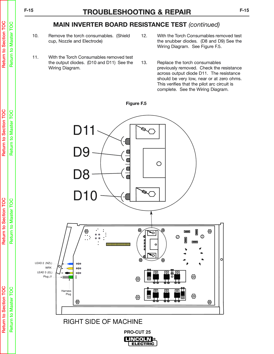
11.With the Torch Consumables removed test the output diodes. (D10 and D11) See the Wiring Diagram.
12.With the Torch Consumables removed test the snubber diodes. (D8 and D9) See the Wiring Diagram. See Figure F.5.
13.Replace the torch consumables previously removed. Check the resistance across output diode D11. The resistance should be very low, near or at zero ohms. This verifies that the pilot arc circuit is complete. See the Wiring Diagram.
Return to Section TOC
Return to Section TOC
Return to Section TOC
Return to Master TOC
Return to Master TOC
Return to Master TOC
Figure F.5
D11
D9 ![]()
![]()
D8 ![]()
![]()
D10 


LEAD 2 (NZL)
WRK
LEAD 3 (EL)
Plug J1
Harness
Plug
