Return to Section TOC
Return to Section TOC
Return to Section TOC
Return to Section TOC
Return to Master TOC
Return to Master TOC
Return to Master TOC
Return to Master TOC
TROUBLESHOOTING & REPAIR | |||
|
|
| |
MAIN INVERTER BOARD RESISTANCE TEST (continued)
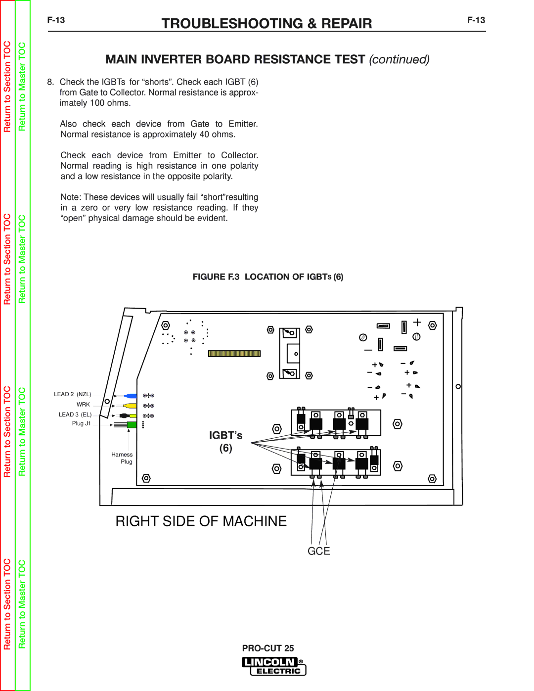
8.Check the IGBTs for “shorts”. Check each IGBT (6) from Gate to Collector. Normal resistance is approx- imately 100 ohms.
Also check each device from Gate to Emitter. Normal resistance is approximately 40 ohms.
Check each device from Emitter to Collector. Normal reading is high resistance in one polarity and a low resistance in the opposite polarity.
Note: These devices will usually fail “short”resulting in a zero or very low resistance reading. If they “open” physical damage should be evident.
FIGURE F.3 LOCATION OF IGBTS (6)
LEAD 2 (NZL)
WRK
LEAD 3 (EL)
Plug J1
IGBT’s
(6)
Harness
Plug
RIGHT SIDE OF MACHINE
GCE