to Section TOC
to Master TOC
THEORY OF OPERATION
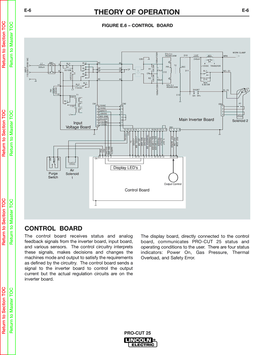
FIGURE E.6 – CONTROL BOARD
INPUT 115/230/1/50/60 VAC
L1 SW1 A 300uH
B |
RL3 |
| RL2 |
R1 |
| RL2 |
10/10W |
| |
F1 |
| |
1A/250V | RL2 |
C26
AC | AC |
| |
CP | CP | CP | |
CP | CP | ||
| |||
AC | AC |
|
R1 ![]()
![]()
CP
R2 ![]()
![]()
15K/3W 15K/3W
1500uF/250V
+
C1a,b
+
C2a,b
Q1a,b,c | D10 | Lout | BS1 |
|
IRG4BC30W | WRK | |||
|
| 240uH | 8A |
|
|
|
|
| |
T2 | SEC |
| +12VDC TRANSFER |
|
PRI |
|
|
| |
C12 | D11 |
| RL1 | NZL (2) |
|
|
|
| |
|
|
| C14 |
|
WORK CLAMP
V1 |
RL2
RL1
| R24 |
Q2a,b,c | 6. 8k/5W |
IRG4BC30W |
|
FN1 | 230VAC | V2 |
|
|
115VAC
L1
T1
230V
RL1
1500uF/250V
| SHUNT | EL (3) | |
C13 | SH- | SH+ |
|
|
| ||
Return to Section TOC
Return to Master TOC
NO | COM | NC |
Purge Switch
115V
L1
Input
Voltage Board
12VDC
Air
Solenoid
1
CN1 | 15VAC |
| CN2 |
|
|
|
|
|
|
|
|
|
|
|
| CN3 | ||
1 |
| 9 |
|
|
|
|
|
|
|
|
|
|
|
| 1 | |||
2 | 15VAC |
| 10 |
|
|
|
|
|
|
|
|
|
|
|
| 2 | ||
3 | SAFETY |
| 5 |
|
|
|
|
|
|
|
|
|
|
|
| 3 | ||
4 | +28VDC |
| 6 |
|
|
|
|
|
|
|
|
|
|
|
| 4 | ||
5 | SEC GND |
| 3 |
|
|
|
|
|
|
|
|
|
|
|
| Main Inverter Board | ||
6 | OVLOAD |
| 22 |
|
|
|
|
|
|
|
|
|
|
|
| |||
7 | 115/230 |
| 2 |
|
|
|
|
|
|
|
|
|
|
|
|
| ||
8 | +12VDC |
| 20 |
|
|
|
|
|
|
|
|
| CN1 |
|
|
| ||
|
|
|
|
| 15 16 12 18 14 1 |
|
|
|
|
|
|
|
|
| 4 | |||
|
|
|
|
| 11 4 | 13 7 | 19 24 21 23 8 | 17 | 1 | 2 | 3 | |||||||
| PS2 | PS1 | SEC GND OVLOAD | SAFETY | V+ EV1 +15Vrms | +12VDC | +8V SW +12VDC SW | SEC GND | OVLOAD | TRANSFER SW | TRANSFER | SOL 1 DRIVER | V OUT OUTPUT TRIGGER SOL 2 DRIVER |
| POT WIPER | POT CW | POT CCW |
|
CN1 | 8 | 6 | 17 9 | 3 | 1 | 2 | 18 14 7 | 15 4 | 11 5 | 16 10 12 13 |
| 23 22 24 |
| |||||
|
|
|
|
|
|
|
|
|
|
|
|
|
|
|
|
|
| |
Display LED's
Output Control
Control Board
PT
12VDC Solenoid 2
to Section TOC
to Master TOC
CONTROL BOARD
The control board receives status and analog feedback signals from the inverter board, input board, and various sensors. The control circuitry interprets these signals, makes decisions and changes the machines mode and output to satisfy the requirements as defined by the circuitry. The control board sends a signal to the inverter board to control the output current but the actual regulation circuits are on the inverter board.
The display board, directly connected to the control board, communicates
Return to Section TOC
Return to Master TOC