Return to Section TOC
Return to Master TOC
TROUBLESHOOTING & REPAIR |
INPUT BOARD REMOVAL & REPLACEMENT (continued)
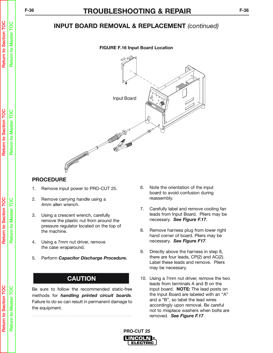
FIGURE F.16 Input Board Location
Return to Section TOC
Return to Master TOC
Input Board | ON | POWER |
|
|
| GAS | PRESSURE |
| |
OFF |
| SAFETY! | ||
PURGE | ||||
|
|
|
| THERMAL |
LIN | CO |
|
|
|
EL |
|
|
| |
ECTLN |
|
|
| |
| RIC |
|
|
|
|
| P |
|
|
|
| R |
|
|
|
| O- |
|
|
|
| C | UT |
|
|
|
| 25 | |
|
|
|
| |
PCT | 20 |
Return to Section TOC
Return to Section TOC
Return to Master TOC
Return to Master TOC
PROCEDURE
1.Remove input power to PRO-CUT 25.
2.Remove carrying handle using a 4mm allen wrench.
3.Using a crescent wrench, carefully remove the plastic nut from around the pressure regulator located on the top of the machine.
4.Using a 7mm nut driver, remove the case wraparound.
5.Perform Capacitor Discharge Procedure.
CAUTION
Be sure to follow the recommended
methods for handling printed circuit boards.
Failure to do so can result in permanent damage to the equipment.
6.Note the orientation of the input board to avoid confusion during reassembly.
7.Carefully label and remove cooling fan leads from Input Board. Pliers may be necessary. See Figure F.17.
8.Remove harness plug from lower right hand corner of board. Pliers may be necessary. See Figure F17.
9.Directly above the harness in step 8, there are four leads, CP(2) and AC(2). Label these leads and remove. Pliers may be necessary.
10.Using a 7mm nut driver, remove the two leads from terminals A and B on the input board. NOTE: The lead posts on the Input Board are labeled with an “A” and a “B”, so label the lead wires accordingly upon removal. Be careful not to misplace washers when bolts are removed. See Figure F.17.