Section TOC
Master TOC
THEORY OF OPERATION
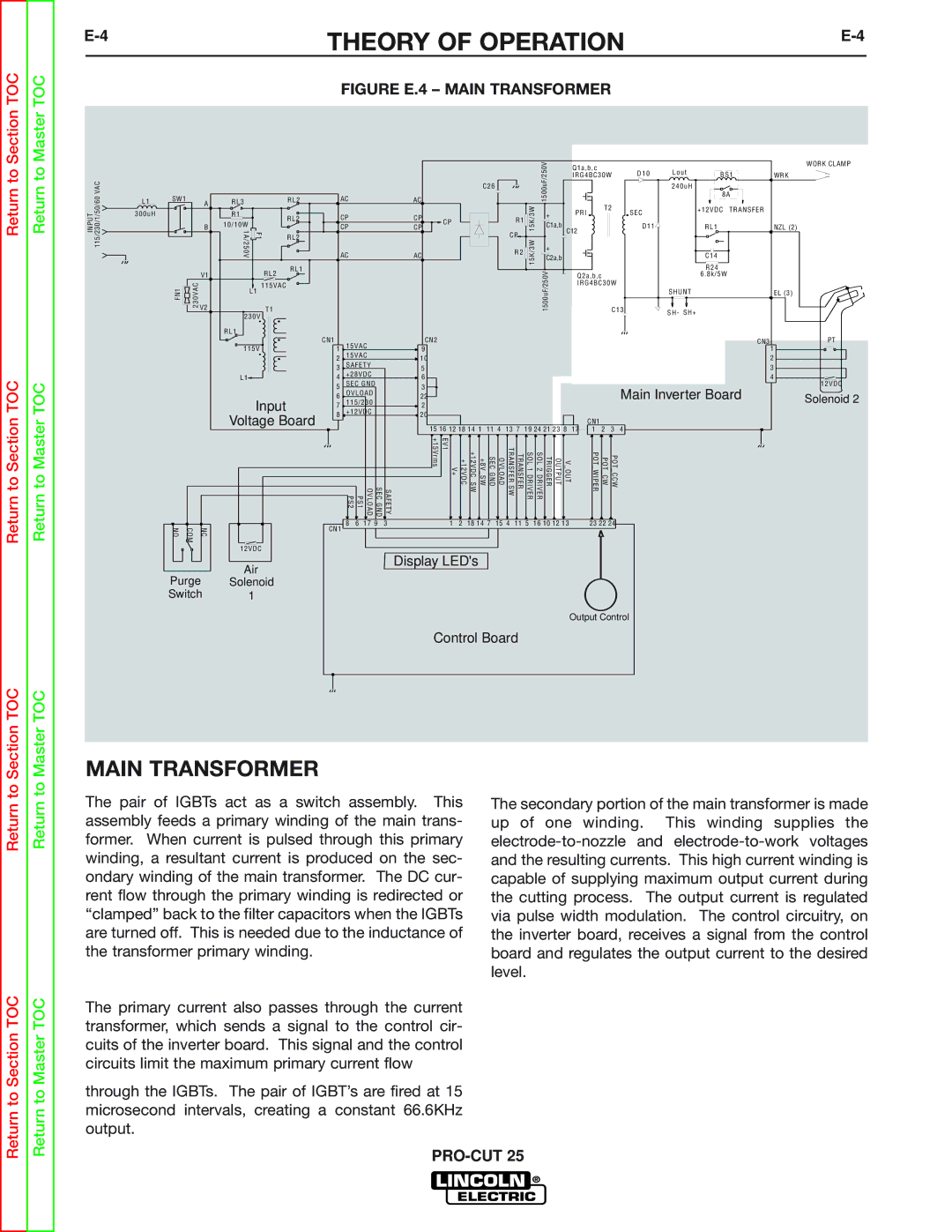
FIGURE E.4 – MAIN TRANSFORMER
INPUT 115/230/1/50/60 VAC
L1 SW1 A 300uH
B |
RL3 |
| RL2 |
R1 |
| RL2 |
10/10W |
| |
F1 |
| |
1A/250V | RL2 | |
|
|
C26
AC | AC |
| |
CP | CP | CP | |
CP | CP | ||
| |||
AC | AC |
|
R1 ![]()
![]()
CP
R2 ![]()
![]()
15K/3W 15K/3W
1500uF/250V
+
C1a,b
+
C2a,b
Q1a,b,c | D10 | Lout | BS1 |
|
IRG4BC30W | WRK | |||
|
| 240uH | 8A |
|
|
|
|
| |
T2 | SEC |
| +12VDC TRANSFER |
|
PRI |
|
|
| |
C12 | D11 |
| RL1 | NZL (2) |
|
|
|
| |
|
|
| C14 |
|
WORK CLAMP
V1 |
RL2
RL1
| R24 |
Q2a,b,c | 6.8k/5W |
IRG4BC30W |
|
FN1 | 230VAC | V2 |
|
|
115VAC
L1
T1
230V
RL1
1500uF/250V
| SHUNT | EL (3) | |
C13 | SH- | SH+ |
|
|
| ||
Return to Section TOC
Return to Master TOC
NO | COM | NC |
Purge Switch
115V
L1
Input
Voltage Board
12VDC
Air
Solenoid
1
CN1 | 15VAC |
| CN2 |
|
|
|
|
|
|
|
|
|
|
|
| CN3 | ||
1 |
| 9 |
|
|
|
|
|
|
|
|
|
|
|
| 1 | |||
2 | 15VAC |
| 10 |
|
|
|
|
|
|
|
|
|
|
|
| 2 | ||
3 | SAFETY |
| 5 |
|
|
|
|
|
|
|
|
|
|
|
| 3 | ||
4 | +28VDC |
| 6 |
|
|
|
|
|
|
|
|
|
|
|
| 4 | ||
5 | SEC GND |
| 3 |
|
|
|
|
|
|
|
|
|
|
|
| Main Inverter Board | ||
6 | OVLOAD |
| 22 |
|
|
|
|
|
|
|
|
|
|
|
| |||
7 | 115/230 |
| 2 |
|
|
|
|
|
|
|
|
|
|
|
|
| ||
8 | +12VDC |
| 20 |
|
|
|
|
|
|
|
|
| CN1 |
|
|
| ||
|
|
|
|
| 15 16 12 18 14 1 |
|
|
|
|
|
|
|
|
| 4 | |||
|
|
|
|
| 11 4 | 13 7 | 19 24 21 23 8 | 17 | 1 | 2 | 3 | |||||||
| PS2 | PS1 | SEC GND OVLOAD | SAFETY | V+ EV1 +15Vrms | +12VDC | +8V SW +12VDC SW | SEC GND | OVLOAD | TRANSFER SW | TRANSFER | SOL 1 DRIVER | V OUT OUTPUT TRIGGER SOL 2 DRIVER |
| POT WIPER | POT CW | POT CCW |
|
CN1 | 8 | 6 | 17 9 | 3 | 1 | 2 | 18 14 7 | 15 4 | 11 5 | 16 10 12 13 |
| 23 22 24 |
| |||||
|
|
|
|
|
|
|
|
|
|
|
|
|
|
|
|
|
| |
Display LED's
Output Control
Control Board
PT
12VDC Solenoid 2
to Section TOC
to Master TOC
MAIN TRANSFORMER
The pair of IGBTs act as a switch assembly. This assembly feeds a primary winding of the main trans- former. When current is pulsed through this primary winding, a resultant current is produced on the sec- ondary winding of the main transformer. The DC cur- rent flow through the primary winding is redirected or “clamped” back to the filter capacitors when the IGBTs are turned off. This is needed due to the inductance of the transformer primary winding.
The primary current also passes through the current transformer, which sends a signal to the control cir- cuits of the inverter board. This signal and the control circuits limit the maximum primary current flow
through the IGBTs. The pair of IGBT’s are fired at 15 microsecond intervals, creating a constant 66.6KHz output.
The secondary portion of the main transformer is made up of one winding. This winding supplies the