Return to Section TOC
Return to Section TOC
Return to Master TOC
Return to Master TOC
TROUBLESHOOTING & REPAIR | |||
|
|
|
|
AIR/GAS SOLENOID TEST (continued)
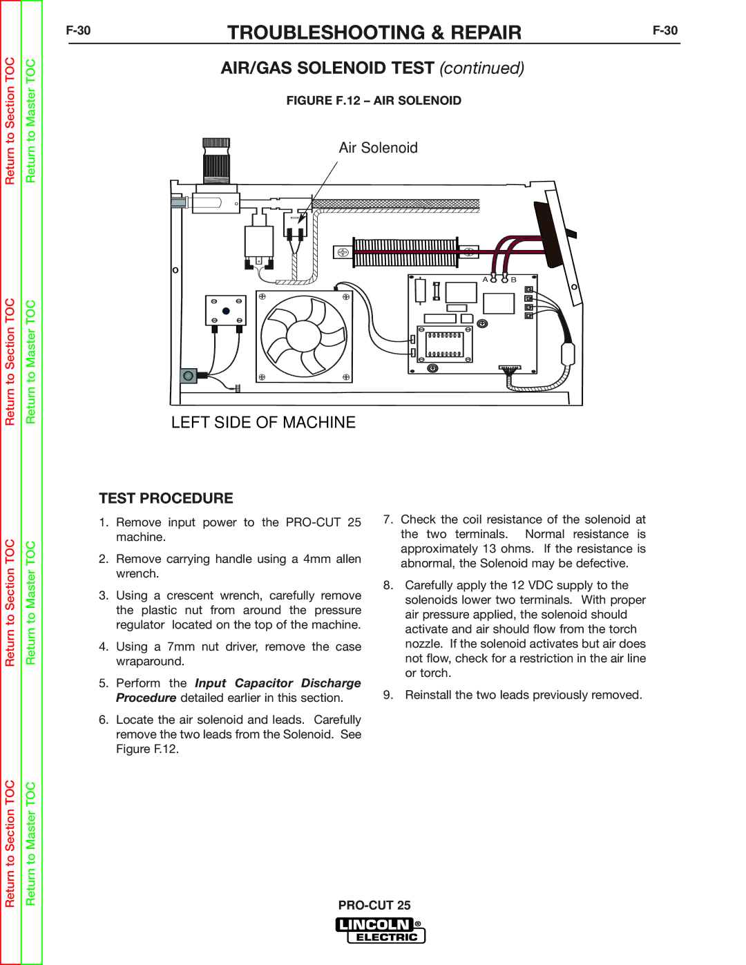
FIGURE F.12 – AIR SOLENOID
Air Solenoid
A B
LEFT SIDE OF MACHINE
Return to Section TOC
Return to Master TOC
TEST PROCEDURE
1.Remove input power to the
2.Remove carrying handle using a 4mm allen wrench.
3.Using a crescent wrench, carefully remove the plastic nut from around the pressure regulator located on the top of the machine.
4.Using a 7mm nut driver, remove the case wraparound.
5.Perform the Input Capacitor Discharge Procedure detailed earlier in this section.
6.Locate the air solenoid and leads. Carefully remove the two leads from the Solenoid. See Figure F.12.
7.Check the coil resistance of the solenoid at the two terminals. Normal resistance is approximately 13 ohms. If the resistance is abnormal, the Solenoid may be defective.
8.Carefully apply the 12 VDC supply to the solenoids lower two terminals. With proper air pressure applied, the solenoid should activate and air should flow from the torch nozzle. If the solenoid activates but air does not flow, check for a restriction in the air line or torch.
9.Reinstall the two leads previously removed.
Return to Section TOC
Return to Master TOC