User Manual version 2503
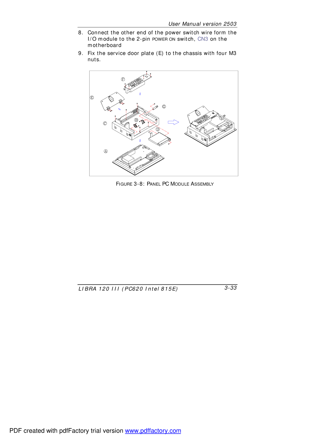
8.Connect the other end of the power switch wire form the I/O module to the
9.Fix the service door plate (E) to the chassis with four M3 nuts.
FIGURE |
LIBRA 120 III (PC620 Intel 815E) |
PDF created with pdfFactory trial version www.pdffactory.com
