User Manual version 2503
4.1.5.Connectors & Pin Assignment
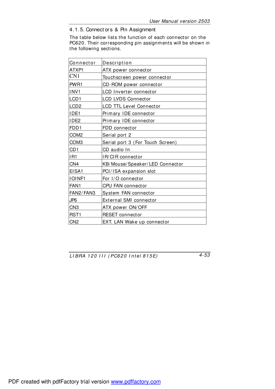
The table below lists the function of each connector on the PC620. Their corresponding pin assignments will be shown in the following sections.
Connector | Description |
ATXP1 | ATX power connector |
CN1 | Touchscreen power connector |
PWR1 | |
INV1 | LCD Inverter connector |
LCD1 | LCD LVDS Connector |
LCD2 | LCD TTL Level Connector |
IDE1 | Primary IDE connector |
IDE2 | Primary IDE connector |
FDD1 | FDD connector |
COM2 | Serial port 2 |
COM3 | Serial port 3 (For Touch Screen) |
CD1 | CD audio In |
IR1 | IR/CIR connector |
CN4 | KB/Mouse/Speaker/LED Connector |
EISA1 | PCI/ISA expansion slot |
IOINF1 | For I/O connector |
FAN1 | CPU FAN connector |
FAN2/FAN3 | System FAN connector |
JP6 | External SMI connector |
CN3 | ATX power ON/OFF |
RST1 | RESET connector |
CN2 | EXT. LAN Wake up connector |
LIBRA 120 III (PC620 Intel 815E) |
PDF created with pdfFactory trial version www.pdffactory.com
