User Manual version 2503
4.1.4.Jumpers & Jumper Setting
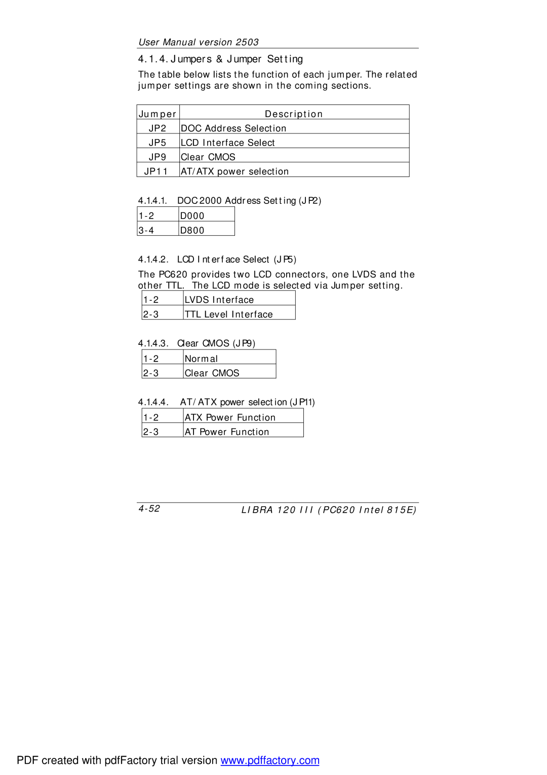
The table below lists the function of each jumper. The related jumper settings are shown in the coming sections.
Jumper | Description |
JP2 | DOC Address Selection |
JP5 | LCD Interface Select |
JP9 | Clear CMOS |
JP11 | AT/ATX power selection |
4.1.4.1.DOC 2000 Address Setting (JP2)
4.1.4.2.LCD Interface Select (JP5)
The PC620 provides two LCD connectors, one LVDS and the other TTL. The LCD mode is selected via Jumper setting.
LVDS Interface | |
TTL Level Interface |
4.1.4.3.Clear CMOS (JP9)
4.1.4.4.AT/ATX power selection (JP11)
LIBRA 120 III (PC620 Intel 815E) |
PDF created with pdfFactory trial version www.pdffactory.com
