VPort 2310 User’s Manual | Introduction |
General I/O terminal block
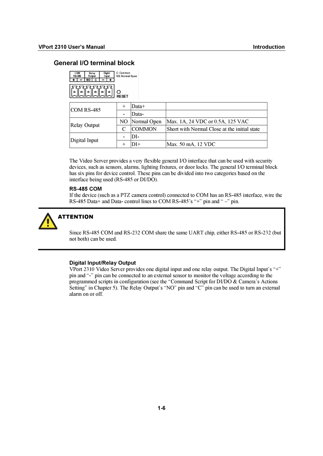
COM | + | Data+ |
| |
- | Data- |
| ||
|
| |||
Relay Output | NO | Normal Open | Max. 1A, 24 VDC or 0.5A, 125 VAC | |
C | COMMON | Short with Normal Close at the initial state | ||
| ||||
Digital Input | - | DI- |
| |
+ | DI+ | Max. 50 mA, 12 VDC | ||
|
The Video Server provides a very flexible general I/O interface that can be used with security devices, such as sensors, alarms, lighting fixtures, or door locks. The general I/O terminal block has six pins for device control. These pins can be divided into two categories based on the interface being used
RS-485 COM
If the device (such as a PTZ camera control) connected to COM has an
![]() ATTENTION
ATTENTION
Since
Digital Input/Relay Output
VPort 2310 Video Server provides one digital input and one relay output. The Digital Input’s “+” pin and