Chapter 1 - Introduction and Description
1.7Modem LED Indicators
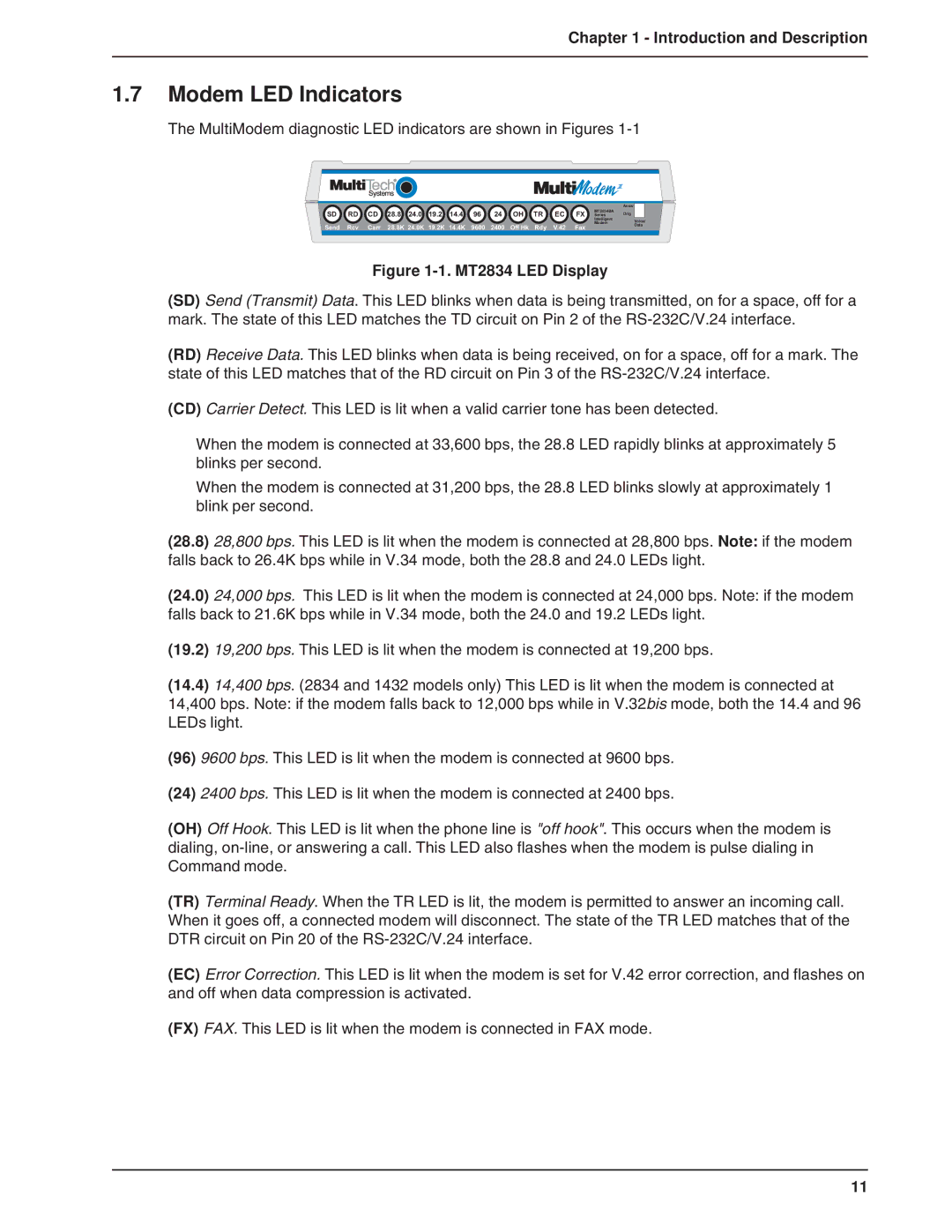
The MultiModem diagnostic LED indicators are shown in Figures 1-1
| SD | RD | CD | 28.8 24.0 | 19.2 | 14.4 | 96 | 24 | OH | TR | EC | FX | MT2834BA | Answ |
|
|
| Orig |
|
| |||||||||||||
| Series |
|
| |||||||||||||
|
|
|
|
|
|
|
|
|
|
|
|
| Intelligent | Voice/ | ||
|
|
|
|
|
|
|
|
|
|
|
|
| Modem | |||
| Send | Rcv | Carr | 28.8K 24.0K | 19.2K | 14.4K | 9600 | 2400 | Off Hk | Rdy | V.42 | Fax | Data | |||
|
| |||||||||||||||
|
|
|
|
| ||||||||||||
Figure 1-1. MT2834 LED Display
(SD) Send (Transmit) Data. This LED blinks when data is being transmitted, on for a space, off for a mark. The state of this LED matches the TD circuit on Pin 2 of the
(RD) Receive Data. This LED blinks when data is being received, on for a space, off for a mark. The state of this LED matches that of the RD circuit on Pin 3 of the
(CD) Carrier Detect. This LED is lit when a valid carrier tone has been detected.
When the modem is connected at 33,600 bps, the 28.8 LED rapidly blinks at approximately 5 blinks per second.
When the modem is connected at 31,200 bps, the 28.8 LED blinks slowly at approximately 1 blink per second.
(28.8) 28,800 bps. This LED is lit when the modem is connected at 28,800 bps. Note: if the modem falls back to 26.4K bps while in V.34 mode, both the 28.8 and 24.0 LEDs light.
(24.0) 24,000 bps. This LED is lit when the modem is connected at 24,000 bps. Note: if the modem falls back to 21.6K bps while in V.34 mode, both the 24.0 and 19.2 LEDs light.
(19.2) 19,200 bps. This LED is lit when the modem is connected at 19,200 bps.
(14.4) 14,400 bps. (2834 and 1432 models only) This LED is lit when the modem is connected at 14,400 bps. Note: if the modem falls back to 12,000 bps while in V.32bis mode, both the 14.4 and 96 LEDs light.
(96)9600 bps. This LED is lit when the modem is connected at 9600 bps.
(24)2400 bps. This LED is lit when the modem is connected at 2400 bps.
(OH) Off Hook. This LED is lit when the phone line is "off hook". This occurs when the modem is dialing,
(TR) Terminal Ready. When the TR LED is lit, the modem is permitted to answer an incoming call. When it goes off, a connected modem will disconnect. The state of the TR LED matches that of the DTR circuit on Pin 20 of the
(EC) Error Correction. This LED is lit when the modem is set for V.42 error correction, and flashes on and off when data compression is activated.
(FX) FAX. This LED is lit when the modem is connected in FAX mode.
11
