Chapter 7 - DIP-Switch Settings

Switch #2

SDLC/BSC Option

(Synchronous Mode/Leased Line/Dial-Up)

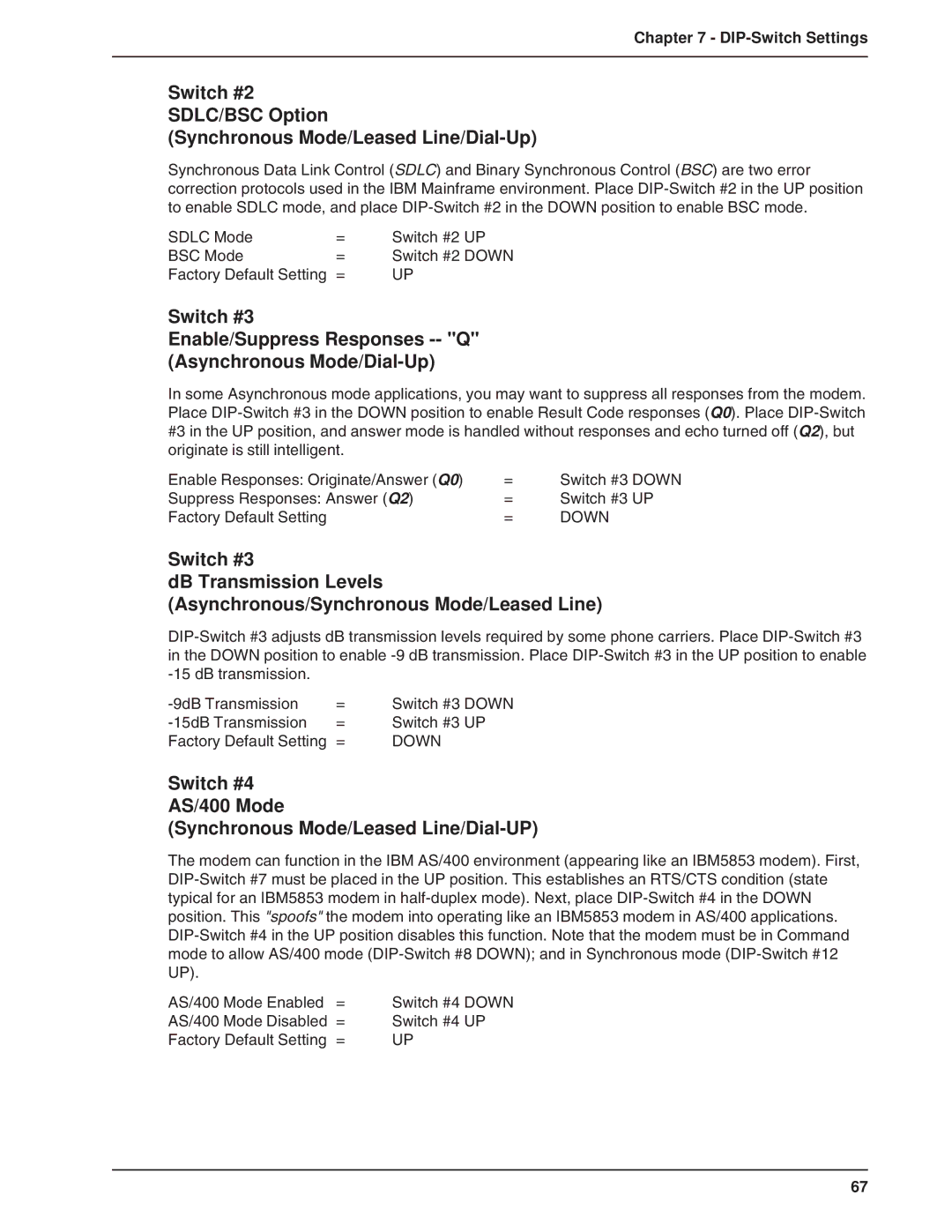
Synchronous Data Link Control (SDLC) and Binary Synchronous Control (BSC) are two error correction protocols used in the IBM Mainframe environment. Place DIP-Switch #2 in the UP position to enable SDLC mode, and place DIP-Switch #2 in the DOWN position to enable BSC mode.

SDLC Mode

=

Switch #2 UP

BSC Mode

=

Switch #2 DOWN

Factory Default Setting

=

UP

Switch #3

Enable/Suppress Responses -- "Q"

(Asynchronous Mode/Dial-Up)

In some Asynchronous mode applications, you may want to suppress all responses from the modem. Place DIP-Switch #3 in the DOWN position to enable Result Code responses (Q0). Place DIP-Switch #3 in the UP position, and answer mode is handled without responses and echo turned off (Q2), but originate is still intelligent.

Enable Responses: Originate/Answer (Q0)

=

Switch #3 DOWN

Suppress Responses: Answer (Q2)

=

Switch #3 UP

Factory Default Setting

=

DOWN

Switch #3

dB Transmission Levels

(Asynchronous/Synchronous Mode/Leased Line)

DIP-Switch #3 adjusts dB transmission levels required by some phone carriers. Place DIP-Switch #3 in the DOWN position to enable -9 dB transmission. Place DIP-Switch #3 in the UP position to enable -15 dB transmission.

-9dB Transmission

=

Switch #3 DOWN

-15dB Transmission

=

Switch #3 UP

Factory Default Setting

=

DOWN

Switch #4

AS/400 Mode

(Synchronous Mode/Leased Line/Dial-UP)

The modem can function in the IBM AS/400 environment (appearing like an IBM5853 modem). First, DIP-Switch #7 must be placed in the UP position. This establishes an RTS/CTS condition (state typical for an IBM5853 modem in half-duplex mode). Next, place DIP-Switch #4 in the DOWN position. This "spoofs" the modem into operating like an IBM5853 modem in AS/400 applications. DIP-Switch #4 in the UP position disables this function. Note that the modem must be in Command mode to allow AS/400 mode (DIP-Switch #8 DOWN); and in Synchronous mode (DIP-Switch #12 UP).

AS/400 Mode Enabled

=

Switch #4 DOWN

AS/400 Mode Disabled =

Switch #4 UP

Factory Default Setting

=

UP

67

Page 67
Image 67
Multi-Tech Systems BA-Series manual Switch #4 AS/400 Mode Synchronous Mode/Leased Line/Dial-UP, DIP-Switch Settings