MultiModemBA User Guide
7.1Introduction
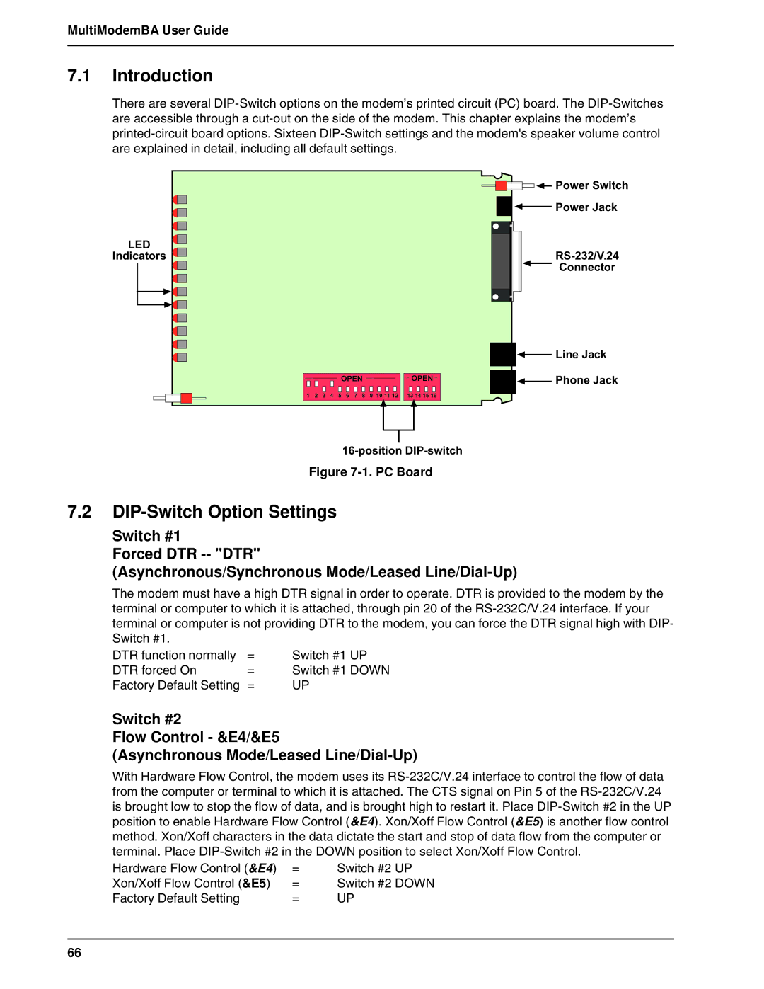
There are several
![]()
![]()
![]()
![]()
![]()
![]() Power Switch
Power Switch
![]()
![]()
![]() Power Jack
Power Jack
LED |
|
|
|
|
|
|
| |||
|
|
|
|
|
|
| ||||
|
|
|
|
|
|
| ||||
|
|
|
|
|
| |||||
Indicators |
|
|
|
|
|
|
| |||
|
|
|
|
|
| |||||
|
|
|
|
|
|
|
|
|
| Connector |
|
|
|
|
|
|
|
|
|
| |
|
|
|
|
|
|
|
|
|
| |
|
|
|
|
|
|
|
|
|
|
|
|
|
|
|
|
|
|
|
|
|
|
|
|
|
|
|
|
|
|
|
|
|
|
|
|
|
|
|
|
|
|
|
|
|
|
|
|
|
|
|
|
|
|
|
|
|
|
|
|
|
|
|
|
|
|
|
|
|
|
|
|
|
|
|
|
|
|
|
|
|
|
|
|
|
|
|
|
OPEN | OPEN |
1 | 2 | 3 | 4 | 5 | 6 | 7 | 8 | 9 | 10 11 12 | 13 14 15 16 |
![]()
![]()
![]() Line Jack
Line Jack ![]()
![]()
![]() Phone Jack
Phone Jack
Figure 7-1. PC Board
7.2DIP-Switch Option Settings
Switch #1
Forced DTR
(Asynchronous/Synchronous Mode/Leased
The modem must have a high DTR signal in order to operate. DTR is provided to the modem by the terminal or computer to which it is attached, through pin 20 of the
DTR function normally DTR forced On Factory Default Setting
=Switch #1 UP
=Switch #1 DOWN
=UP
Switch #2
Flow Control - &E4/&E5
(Asynchronous Mode/Leased
With Hardware Flow Control, the modem uses its
Hardware Flow Control (&E4) | = | Switch #2 UP |
Xon/Xoff Flow Control (&E5) | = | Switch #2 DOWN |
Factory Default Setting | = | UP |
66