8.Power on your computer. A CMOS Checksum message appears and prompts you to press F1 to enter Setup.
9.Press F1 to enter Setup and restore the default parameter settings.
10.Be sure to modify any custom settings that you may have configured.
11.Disable the BIOS flash switch. Change switch 5 back to “OFF” after completing the BIOS update. For details about enabling and disabling the BIOS flash switch, see the section earlier in this chapter, “Enabling the BIOS Flash Switch.”
Configuring the Switch Settings
Some system settings are set through DIP switches. The
See the following sections for information on accessing the DIP switches and identifying DIP switch settings.
Accessing the DIP Switch
Follow these steps to access the DIP switch in the memory bay.
1.Power off the system and disconnect any peripheral devices.
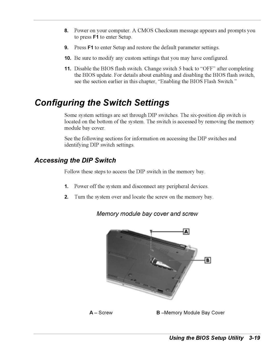
2.Turn the system over and locate the screw on the memory bay.
Memory module bay cover and screw
A – Screw | B |