Chapter 6 LEDs: support and diagnostic functions 63
LEDs 1 through 8 and the Power LED during operation
After the
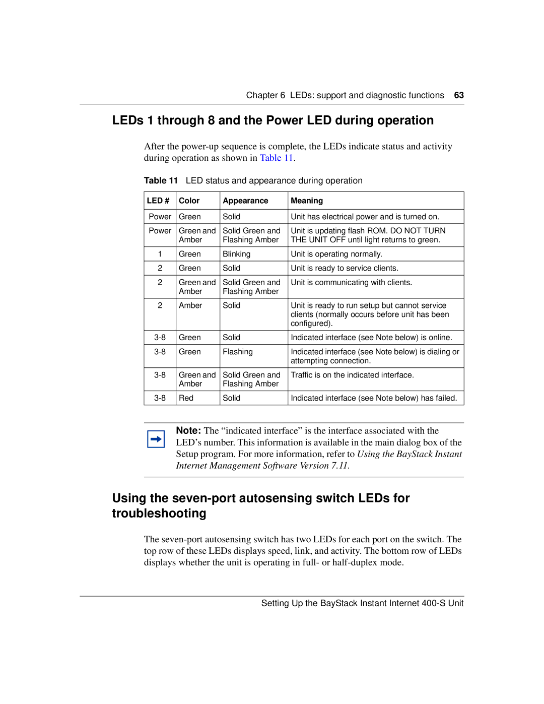
Table 11 LED status and appearance during operation
LED # | Color | Appearance | Meaning |
|
|
|
|
Power | Green | Solid | Unit has electrical power and is turned on. |
|
|
|
|
Power | Green and | Solid Green and | Unit is updating flash ROM. DO NOT TURN |
| Amber | Flashing Amber | THE UNIT OFF until light returns to green. |
|
|
|
|
1 | Green | Blinking | Unit is operating normally. |
|
|
|
|
2 | Green | Solid | Unit is ready to service clients. |
|
|
|
|
2 | Green and | Solid Green and | Unit is communicating with clients. |
| Amber | Flashing Amber |
|
|
|
|
|
2 | Amber | Solid | Unit is ready to run setup but cannot service |
|
|
| clients (normally occurs before unit has been |
|
|
| configured). |
|
|
|
|
Green | Solid | Indicated interface (see Note below) is online. | |
|
|
|
|
Green | Flashing | Indicated interface (see Note below) is dialing or | |
|
|
| attempting connection. |
|
|
|
|
Green and | Solid Green and | Traffic is on the indicated interface. | |
| Amber | Flashing Amber |
|
|
|
|
|
Red | Solid | Indicated interface (see Note below) has failed. | |
|
|
|
|
Note: The “indicated interface” is the interface associated with the LED’s number. This information is available in the main dialog box of the Setup program. For more information, refer to Using the BayStack Instant Internet Management Software Version 7.11.
Using the
The