36 Chapter 3 Instant Internet
•Seven 10/100 Link/Activity LEDs (labeled
•Seven FDX LEDs (labeled
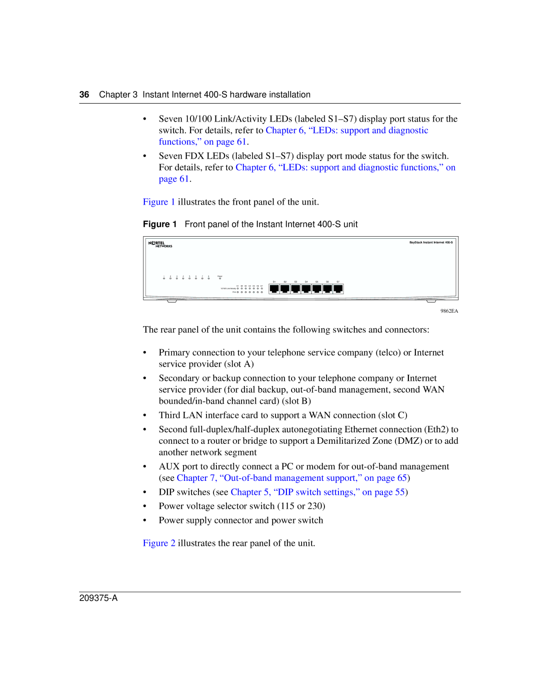
Figure 1 illustrates the front panel of the unit.
Figure 1 Front panel of the Instant Internet 400-S unit
BayStack Instant Internet
1 | 2 | 3 | 4 | 5 | 6 | 7 | 8 | Power |
S1 | S2 | S3 | S4 | S5 | S6 | S7 |
S1 S2 S3 S4 S5 S6 S7
10/100 Link/Activity ![]()
FDX ![]()
9862EA
The rear panel of the unit contains the following switches and connectors:
•Primary connection to your telephone service company (telco) or Internet service provider (slot A)
•Secondary or backup connection to your telephone company or Internet service provider (for dial backup,
•Third LAN interface card to support a WAN connection (slot C)
•Second
•AUX port to directly connect a PC or modem for
•DIP switches (see Chapter 5, “DIP switch settings,” on page 55)
•Power voltage selector switch (115 or 230)
•Power supply connector and power switch