38Chapter 4 Power supply installation
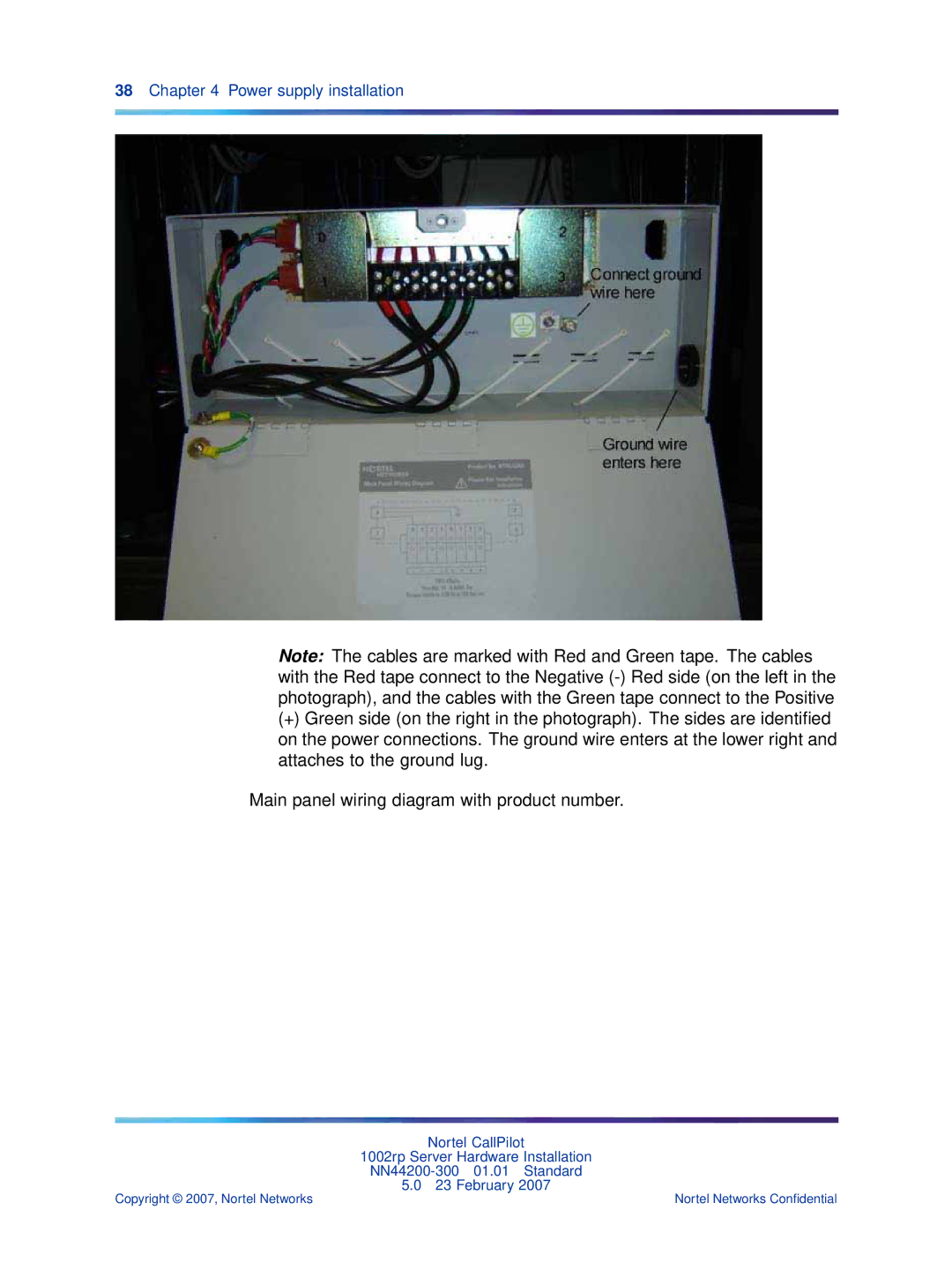
Note: The cables are marked with Red and Green tape. The cables with the Red tape connect to the Negative
(+)Green side (on the right in the photograph). The sides are identified on the power connections. The ground wire enters at the lower right and attaches to the ground lug.
Main panel wiring diagram with product number.
Nortel CallPilot
1002rp Server Hardware Installation
5.0 23 February 2007
Copyright © 2007, Nortel Networks | Nortel Networks Confidential |
