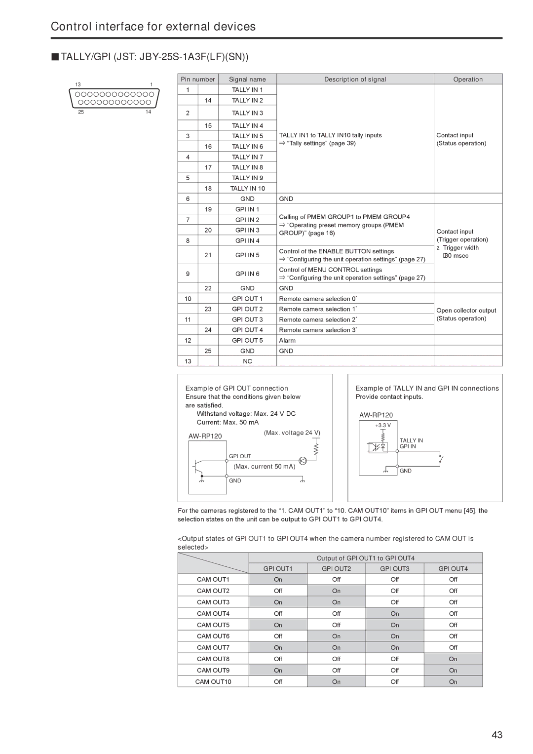
Control interface for external devices TALLY/GPI (JST:
13 | 1 | Pin number | Signal name | Description of signal | Operation | |
|
| 1 |
| TALLY IN 1 |
|
|
|
|
| 14 | TALLY IN 2 |
|
|
25 | 14 | 2 |
| TALLY IN 3 |
|
|
|
|
|
|
|
|
|
|
|
| 15 | TALLY IN 4 |
|
|
|
| 3 |
| TALLY IN 5 | TALLY IN1 to TALLY IN10 tally inputs | Contact input |
|
|
|
|
| ⇒ “Tally settings” (page 39) | (Status operation) |
|
|
| 16 | TALLY IN 6 | ||
|
|
|
|
| ||
|
| 4 |
| TALLY IN 7 |
|
|
|
|
| 17 | TALLY IN 8 |
|
|
|
| 5 |
| TALLY IN 9 |
|
|
|
|
| 18 | TALLY IN 10 |
|
|
|
| 6 |
| GND | GND |
|
|
|
| 19 | GPI IN 1 | Calling of PMEM GROUP1 to PMEM GROUP4 |
|
|
| 7 |
| GPI IN 2 |
| |
|
|
| ⇒ “Operating preset memory groups (PMEM |
| ||
|
|
| 20 | GPI IN 3 | Contact input | |
|
|
| GROUP)” (page 16) | |||
|
| 8 |
| GPI IN 4 |
| (Trigger operation) |
|
|
|
|
|
| zzTrigger width |
|
|
| 21 | GPI IN 5 | Control of the ENABLE BUTTON settings | |
|
|
| 30 msec | |||
|
|
| ⇒ “Configuring the unit operation settings” (page 27) | |||
|
|
|
|
|
| |
|
| 9 |
| GPI IN 6 | Control of MENU CONTROL settings |
|
|
|
| ⇒ “Configuring the unit operation settings” (page 27) |
| ||
|
|
|
|
|
| |
|
|
| 22 | GND | GND |
|
|
| 10 |
| GPI OUT 1 | Remote camera selection 0* |
|
|
|
| 23 | GPI OUT 2 | Remote camera selection 1* | Open collector output |
|
| 11 |
| GPI OUT 3 | Remote camera selection 2* | (Status operation) |
|
|
| 24 | GPI OUT 4 | Remote camera selection 3* |
|
|
| 12 |
| GPI OUT 5 | Alarm |
|
|
|
| 25 | GND | GND |
|
|
| 13 |
| NC |
|
|
Example of GPI OUT connection Ensure that the conditions given below are satisfied.
Withstand voltage: Max. 24 V DC
Current: Max. 50 mA
AW‑RP120 | (Max.. voltage 24 V) | |
|
| |
GPI OUT
(Max.. current 50 mA)
GND
Example of TALLY IN and GPI IN connections
Provide contact inputs.
AW‑RP120
+3.3 V
TALLY IN
GPI IN
GND
For the cameras registered to the “1. CAM OUT1” to “10. CAM OUT10” items in GPI OUT menu [45], the selection states on the unit can be output to GPI OUT1 to GPI OUT4.
<Output states of GPI OUT1 to GPI OUT4 when the camera number registered to CAM OUT is selected>
|
| Output of GPI OUT1 to GPI OUT4 |
| |
| GPI OUT1 | GPI OUT2 | GPI OUT3 | GPI OUT4 |
CAM OUT1 | On | Off | Off | Off |
CAM OUT2 | Off | On | Off | Off |
CAM OUT3 | On | On | Off | Off |
CAM OUT4 | Off | Off | On | Off |
CAM OUT5 | On | Off | On | Off |
CAM OUT6 | Off | On | On | Off |
CAM OUT7 | On | On | On | Off |
CAM OUT8 | Off | Off | Off | On |
CAM OUT9 | On | Off | Off | On |
CAM OUT10 | Off | On | Off | On |
43