Control interface for external devices (continued)
Registering camera numbers to CAM OUT1 to CAM OUT10
1. | Press the MENU button.. |
2. | Open GPI OUT menu [45].. |
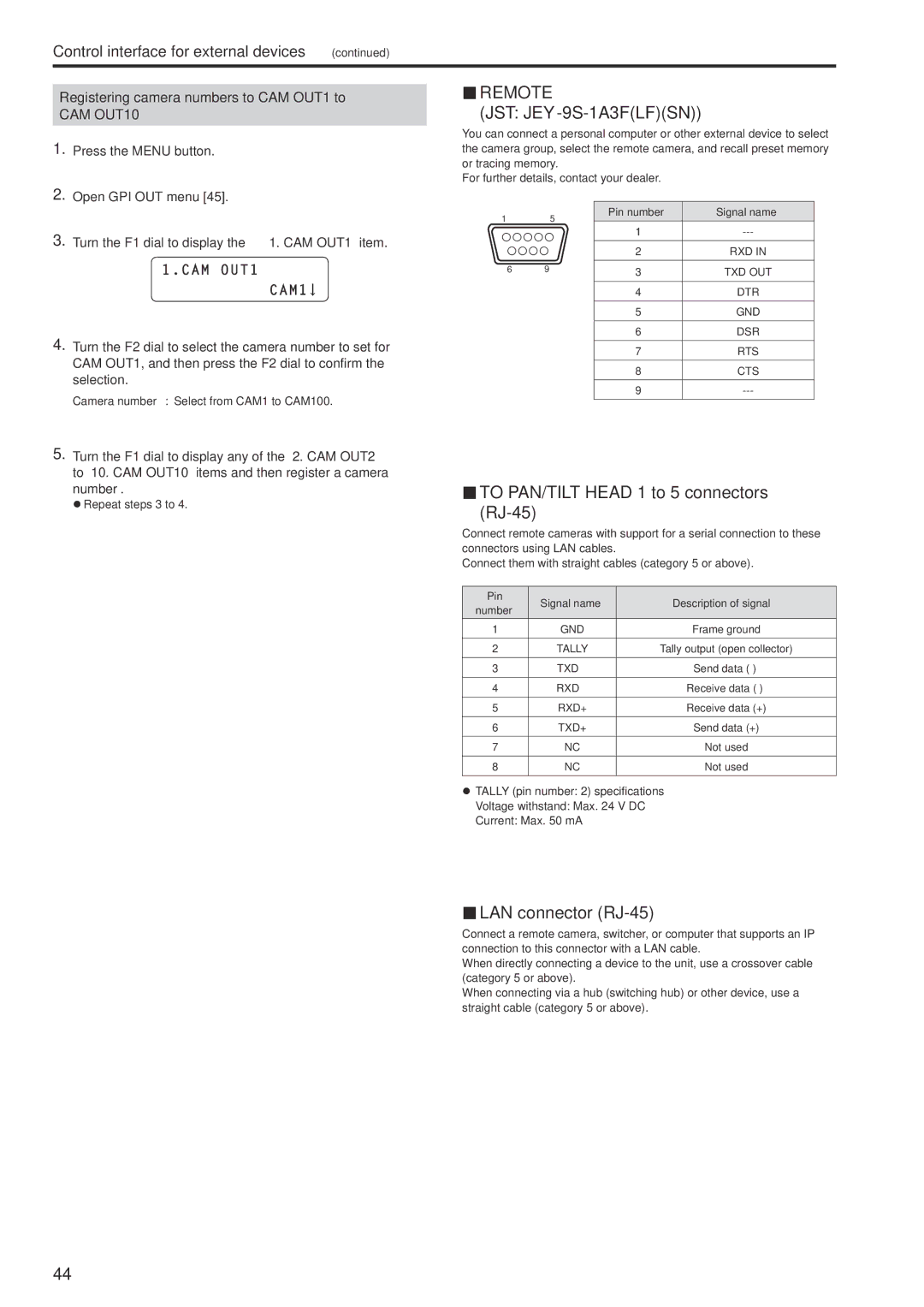
REMOTE
(JST: JEY-9S-1A3F(LF)(SN))
You can connect a personal computer or other external device to select the camera group, select the remote camera, and recall preset memory or tracing memory.
For further details, contact your dealer.
3. Turn the F1 dial to display the “1. CAM OUT1” item.. |
1.CAM OUT1 |
CAM1 ![]()
4. | Turn the F2 dial to select the camera number to set for |
| CAM OUT1, and then press the F2 dial to confirm the |
| selection.. |
| Camera number : Select from CAM1 to CAM100. |
5. | Turn the F1 dial to display any of the “2. CAM OUT2” |
| to “10. CAM OUT10” items and then register a camera |
15
6 9
Pin number | Signal name |
1
2RXD IN
3TXD OUT
4DTR
5GND
6DSR
7RTS
8CTS
9
number.. |
zzRepeat steps 3 to 4. |
TO PAN/TILT HEAD 1 to 5 connectors (RJ-45)
Connect remote cameras with support for a serial connection to these connectors using LAN cables.
Connect them with straight cables (category 5 or above).
Pin | Signal name | Description of signal | |
number | |||
|
| ||
1 | GND | Frame ground | |
2 | TALLY | Tally output (open collector) | |
3 | TXD – | Send data | |
4 | RXD – | Receive data | |
5 | RXD+ | Receive data (+) | |
6 | TXD+ | Send data (+) | |
7 | NC | Not used | |
8 | NC | Not used |
zzTALLY (pin number: 2) specifications Voltage withstand: Max. 24 V DC Current: Max. 50 mA
LAN connector (RJ-45)
Connect a remote camera, switcher, or computer that supports an IP connection to this connector with a LAN cable.
When directly connecting a device to the unit, use a crossover cable (category 5 or above).
When connecting via a hub (switching hub) or other device, use a straight cable (category 5 or above).
44
