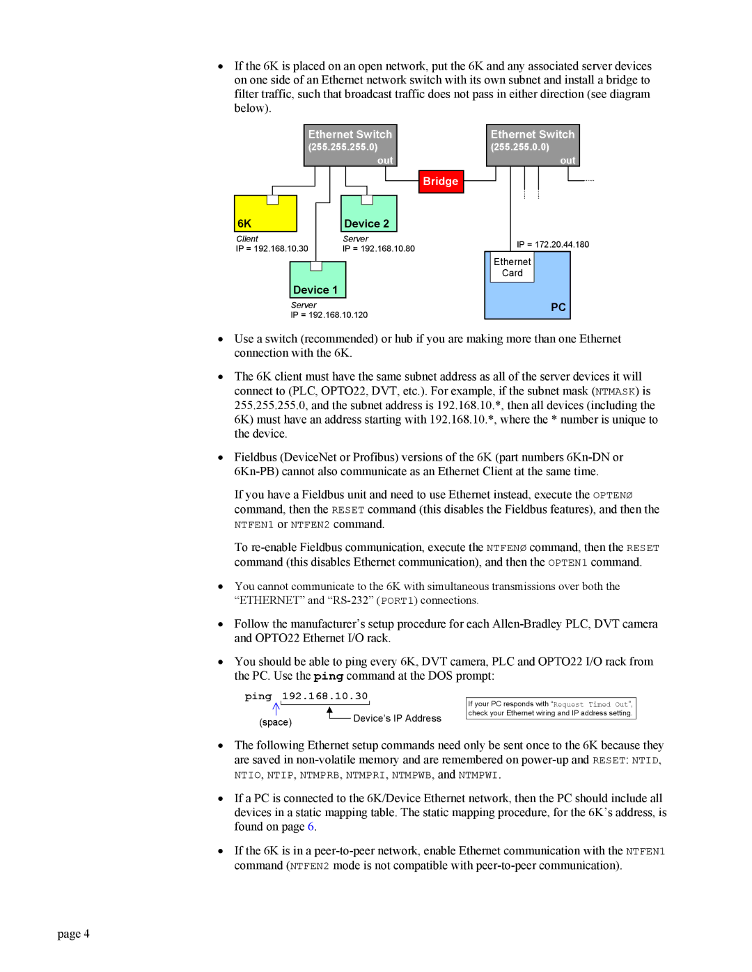
•If the 6K is placed on an open network, put the 6K and any associated server devices on one side of an Ethernet network switch with its own subnet and install a bridge to filter traffic, such that broadcast traffic does not pass in either direction (see diagram below).
Ethernet Switch
(255.255.255.0) out
Bridge
6K | Device 2 |
Client | Server |
IP = 192.168.10.30 | IP = 192.168.10.80 |
Device 1 |
Server
IP = 192.168.10.120
Ethernet Switch
(255.255.0.0)
out
IP = 172.20.44.180
Ethernet
Card
PC
•Use a switch (recommended) or hub if you are making more than one Ethernet connection with the 6K.
•The 6K client must have the same subnet address as all of the server devices it will connect to (PLC, OPTO22, DVT, etc.). For example, if the subnet mask (NTMASK) is 255.255.255.0, and the subnet address is 192.168.10.*, then all devices (including the 6K) must have an address starting with 192.168.10.*, where the * number is unique to the device.
•Fieldbus (DeviceNet or Profibus) versions of the 6K (part numbers
If you have a Fieldbus unit and need to use Ethernet instead, execute the OPTENØ command, then the RESET command (this disables the Fieldbus features), and then the
NTFEN1 or NTFEN2 command.
To
•You cannot communicate to the 6K with simultaneous transmissions over both the “ETHERNET” and
•Follow the manufacturer’s setup procedure for each
•You should be able to ping every 6K, DVT camera, PLC and OPTO22 I/O rack from the PC. Use the ping command at the DOS prompt:
ping 192.168.10.30
(space) |
| Device’s IP Address |
| ||
|
|
If your PC responds with “Request Timed Out”, check your Ethernet wiring and IP address setting.
•The following Ethernet setup commands need only be sent once to the 6K because they are saved in
NTIO, NTIP, NTMPRB, NTMPRI, NTMPWB, and NTMPWI.
•If a PC is connected to the 6K/Device Ethernet network, then the PC should include all devices in a static mapping table. The static mapping procedure, for the 6K’s address, is found on page 6.
•If the 6K is in a
page 4
