NTIO command to specify the type of module in that position.
n \ m NTIO <i>
Network Server #
Range:
Module # on Server “n” Range:
![]() Module Type. Options are: 1 = Digital/Discrete Inputs
Module Type. Options are: 1 = Digital/Discrete Inputs
2 = Digital/Discrete Outputs
3 = Analog Inputs
4 = Analog Outputs
For example, if there is a digital input module in slot 0, then the command would be 3\0NTIO1. If there is an Analog Input module in slot 7, then the command would be 3\7NTIO3.
7.Set the polling rate with the NTPOLL command. 50 milliseconds is recommended. For example, to set the polling rate to 50 ms on server #3, use the 3NTPOLL50 command. If there is an error during polling, then Error Status bit #24 will be set.
Example | NTADDR172,34,54,123 | ; Set the IP address of the 6K |
| |
| OPTEN0 | ; Disable the option card (for Fieldbus units only) | ||
| RESET | ; Enable network function on 6K |
| |
| NTFEN2 |
| ||
| RESET |
|
|
|
| DEL OPTOSU |
|
|
|
| DEF OPTOSU | ; Identify an OPTO22 device as | Server #2, which is | |
| 2NTIP2,172,34,54,124 | |||
| 2NTCONN1 | ; located at IP address 172.34.54.124 | ||
| ; Attempt connection to Server | #2 (OPTO22) | ||
| 2\1NTIO2 | ; Configure OPTO22 module 1 | as | digital output |
| 2\2NTIO2 | ; Configure OPTO22 module 2 | as | digital output |
| 2\3NTIO1 | ; Configure OPTO22 module 3 | as | digital input |
| 2\4NTIO3 | ; Configure OPTO22 module 4 | as | analog input |
| 2NTPOLL50 | ; Begin polling, set polling interval to 50 ms | ||
Program | END |
|
|
|
Once the OPTO22 is configured and a connection is made, you can then set outputs and check | ||||
Interaction | inputs. |
|
|
|
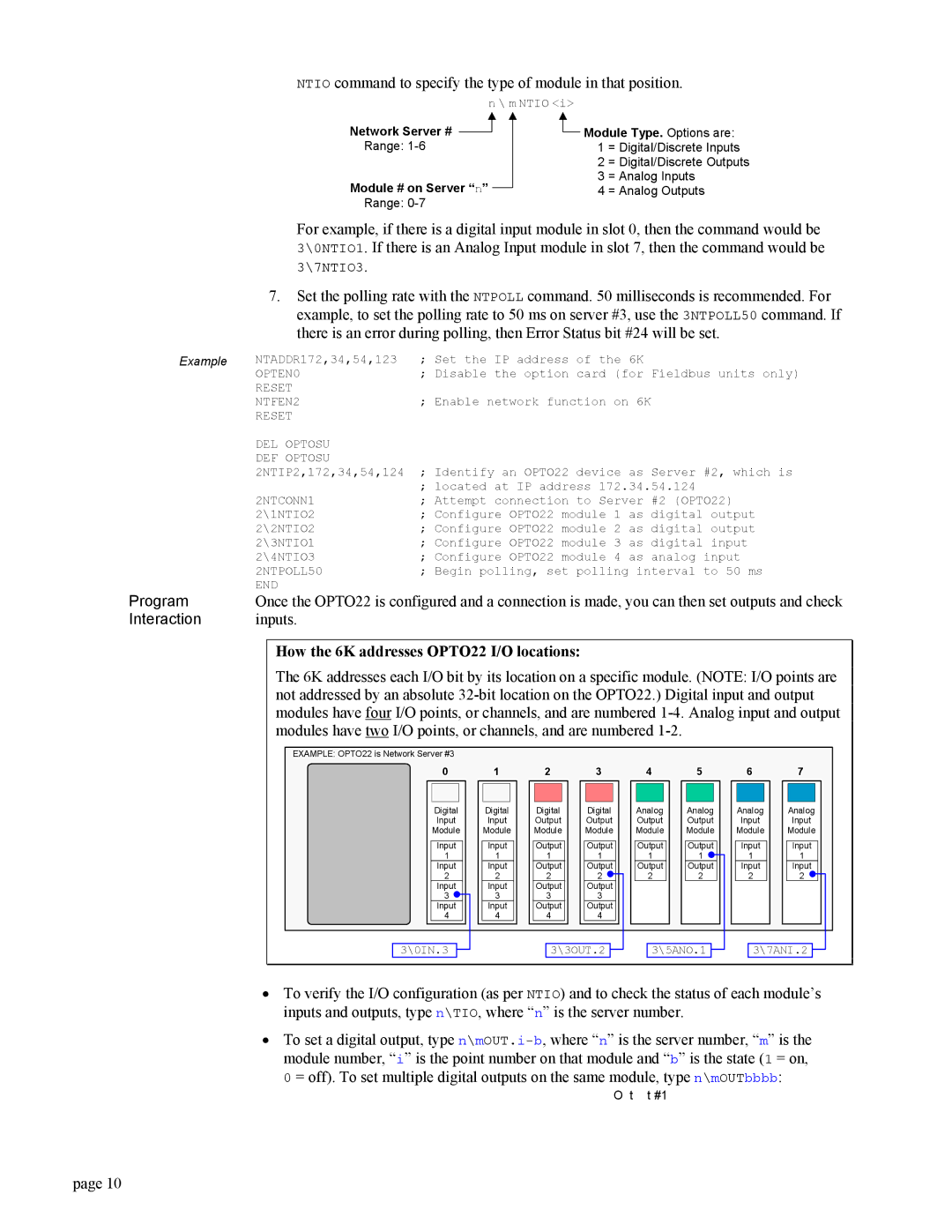
How the 6K addresses OPTO22 I/O locations:
The 6K addresses each I/O bit by its location on a specific module. (NOTE: I/O points are not addressed by an absolute
EXAMPLE: OPTO22 is Network Server #3
0 | 1 | 2 | 3 | 4 | 5 | 6 | 7 | |||||||
Digital |
| Digital |
| Digital |
| Digital |
| Analog |
| Analog |
| Analog |
| Analog |
Input |
| Input |
| Output |
| Output |
| Output |
| Output |
| Input |
| Input |
Module |
| Module |
| Module |
| Module |
| Module |
| Module |
| Module |
| Module |
Input | Input | Output | Output | Output | Output | Input | Input |
1 | 1 | 1 | 1 | 1 | 1 | 1 | 1 |
Input | Input | Output | Output | Output | Output | Input | Input |
2 | 2 | 2 | 2 | 2 | 2 | 2 | 2 |
Input | Input | Output | Output |
|
|
|
|
3 | 3 | 3 | 3 |
|
|
|
|
Input | Input | Output | Output |
|
|
|
|
4 | 4 | 4 | 4 |
|
|
|
|
| 3\0IN.3 |
|
| 3\3OUT.2 |
|
| 3\5ANO.1 |
|
| 3\7ANI.2 |
|
|
|
|
|
|
|
| |||||||
|
|
|
|
|
|
|
|
|
|
|
|
|
•To verify the I/O configuration (as per NTIO) and to check the status of each module’s inputs and outputs, type n\TIO, where “n” is the server number.
•To set a digital output, type
0 = off). To set multiple digital outputs on the same module, type n\mOUTbbbb:
O t t #1
page 10