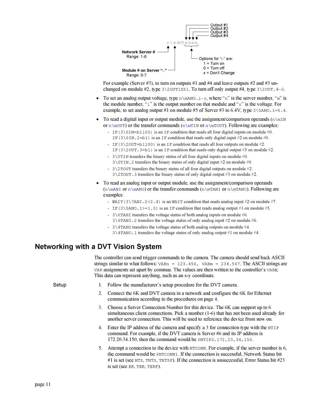
Output #1
Output #2
Output #3
Output #4
n \ m OUT b b b b
Network Server #
Range:
Module # on Server “n” Range: 0-7
![]() Options for “b” are: 1 = Turn on
Options for “b” are: 1 = Turn on
0 = Turn off
x = Don’t Change
For example (Server #3), to turn on outputs #1 and #4 and leave outputs #2 and #3 un- changed on module #2, type 3\2OUT1XX1. To turn off only output #4, type
•To set an analog output voltage, type
•To read a digital input or output module, use the assignment/comparison operands (n\mIN or n\mOUT) or the transfer commands (n\mTIN or n\mTOUT). Following are examples:
-IF(3\0IN=b1100) is an IF condition that reads all four digital inputs on module #0. IF(3\0IN.2=b1) is an IF condition that reads only digital input #2 on module #0.
-IF(3\2OUT=b1100) is an IF condition that reads all four outputs on module #2. IF(3\2OUT.3=b1) is an IF condition that reads only digital output #3 on module #2.
-3\0TIN transfers the binary status of all four digital inputs on module #0. 3\0TIN.2 transfers the binary status of only digital input #2 on module #0.
-3\2TOUT transfers the binary status of all four digital outputs on module #2. 3\2TOUT.3 transfers the binary status of only digital output #3 on module #2.
•To read an analog input or output module, use the assignment/comparison operands
(n\mANI or n\mANO) or the transfer commands (n\mTANI or n\mTANO). Following are examples:
-WAIT(3\7ANI.2<2.4) is an WAIT condition that reads analog input #2 on module #7.
-IF(3\5ANO.1>=1.0) is an IF condition that reads analog output #1 on module #5.
-3\6TANI transfers the voltage status of both analog inputs on module #6. 3\6TANI.2 transfers the voltage status of only analog input #2 on module #6.
-3\4TANO transfers the voltage status of both analog outputs on module #4. 3\4TANO.1 transfers the voltage status of only analog output #1 on module #4.
Networking with a DVT Vision System
The controller can send trigger commands to the camera. The camera should send back ASCII strings similar to what follows: VARn = 123.456, VARm = 234.567. The ASCII strings are VAR assignments set apart by commas. The values are then written to the controller’s VARs; This data can represent anything, such as an
Setup | 1. | Follow the manufacturer’s setup procedure for the DVT camera. |
| 2. | Connect the 6K and DVT camera in a network and configure the 6K for Ethernet |
|
| communication according to the procedures on page 4. |
| 3. | Choose a Server Connection Number for this device. The 6K can support up to 6 |
|
| simultaneous client connections. Pick a number |
|
| another server connection. This will be used to reference the device from now on. |
| 4. | Enter the IP address of the camera and specify a 3 for connection type with the NTIP |
|
| command. For example, if the DVT camera is Server #6 and its IP address is |
|
| 172.20.34.150, then the command would be 6NTIP3,172,20,34,150. |
| 5. | Attempt a connection to the device with NTCONN. For example, if the server number is 6, |
|
| the command would be 6NTCONN1. If the connection is successful, Network Status bit |
|
| #1 is set (see NTS, TNTS, TNTSF). If the connection is unsuccessful, Error Status bit #23 |
|
| is set (see ER, TER, TERF). |
page 11