Example | 6NTIP3,172,34,54,150 | ; Identify a | DVT camera as Server #6, | located at | ||
| 6NTCONN1 | ; | IP address | 172.34.54.150. | Server #6 |
|
| ; | Attempt the connection to |
| |||
Program
Interaction
Example
Once a connection has been established, you can write trigger commands to the camera using the NTWRIT command.
DEL DVT |
|
|
|
DEF DVT | ; | Attempt connection to DVT camera |
|
6NTCONN1 | camera | ||
6NTWRIT"DVT commands" | ; | Write the text "DVT commands" to | |
END |
|
|
|
Networking with an Allen-Bradley SLC 5/05 PLC
The
(50 write, 50 read).
Setup | 1. | Follow the manufacturer’s setup procedure for each |
|
| and OPTO22 Ethernet I/O rack. |
| 2. | Connect the 6K and |
|
| communication according to the procedures on page 4. |
| 3. | Choose a connection number for this device. The 6K can support up to 6 simultaneous |
|
| client connections. Pick a number |
|
| connection. The number is used to reference the device from now on. |
| 4. | Enter the IP address of the PLC and specify a 1 for connection type with the NTIP |
|
| command. For example, if the PLC is Server #5 and its IP address is 172.20.34.124, then |
|
| the command would be 3NTIP1,172,20,34,124. |
| 5. | Attempt a connection to the device with NTCONN. For example, if the server number is 5, |
|
| the command would be 5NTCONN1. If the connection is successful, Network Status bit |
|
| #1 is set (see NTS, TNTS, TNTSF). If the connection is unsuccessful, Error Status bit #23 |
|
| is set (see ER, TER, TERF). |
| 6. | Map the required integer and binary variables between the 6K and the data files in the |
|
| |
|
| provided below). |
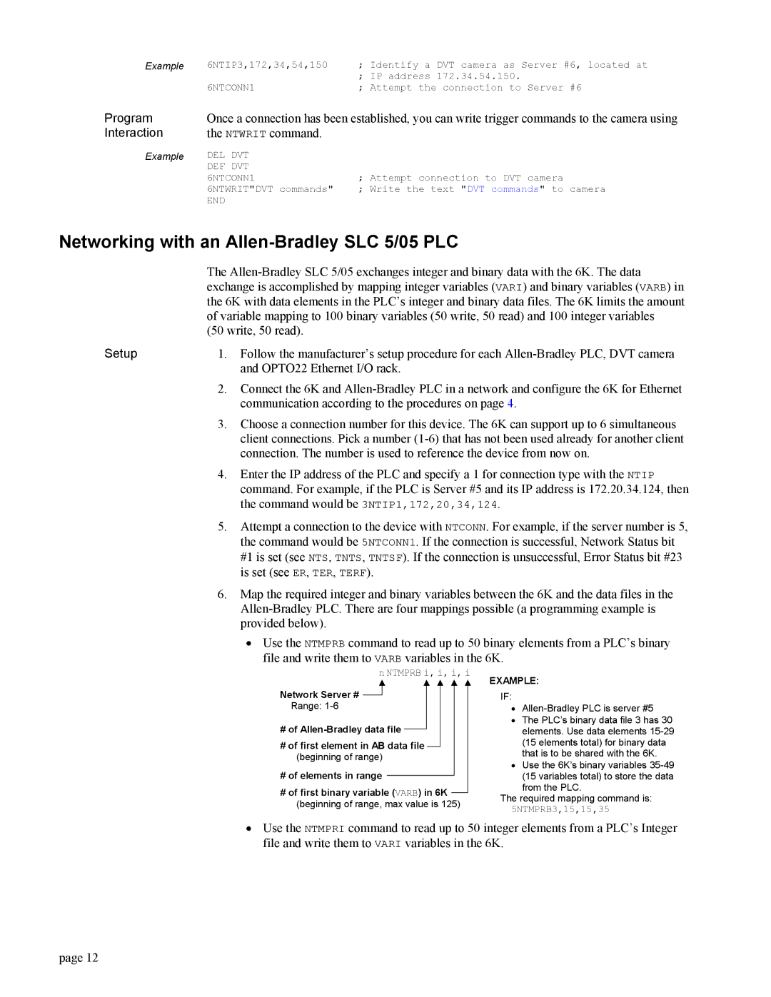
• Use the NTMPRB command to read up to 50 binary elements from a PLC’s binary file and write them to VARB variables in the 6K.
n NTMPRB i, i, i, i
Network Server #
Range:
#of
#of first element in AB data file (beginning of range)
#of elements in range
#of first binary variable (VARB) in 6K (beginning of range, max value is 125)
EXAMPLE:
IF:
•
•The PLC’s binary data file 3 has 30 elements. Use data elements
•Use the 6K’s binary variables
from the PLC.
The required mapping command is:
5NTMPRB3,15,15,35
•Use the NTMPRI command to read up to 50 integer elements from a PLC’s Integer file and write them to VARI variables in the 6K.
page 12