\TANO
Type:
Syntax:
Units:
Range:
Default:
Response:
See Also:
Transfer Network Analog Output Status
Network; Transfer | Product | Rev | |||
<!>n\mTANO<.i> | 6K | 5.3 | |||
n = network server # |
|
| |||
m | = | module | # |
|
|
i | = | analog | output # on module “m” (for |
|
|
(The response represents volts DC.)
n=
1\1TANO: *2.42,3.32
1\1TANO.2: *3.32
\ANO, [ \ANO ], NTIO, \TIO
The \TANO command returns the voltage commanded at one of the network analog outputs (the voltage is commanded with the \ANO command). The network server number and module number must precede the \TANO command (e.g., 2\3ANO reports the voltage commanded on all analog outputs on module 3 of network server 2).
If the status of a specific analog output is required, use the bit select operator (.). For example, 1\3TANO.2 reports the voltage of analog output 2 on module 3 of network server 1.
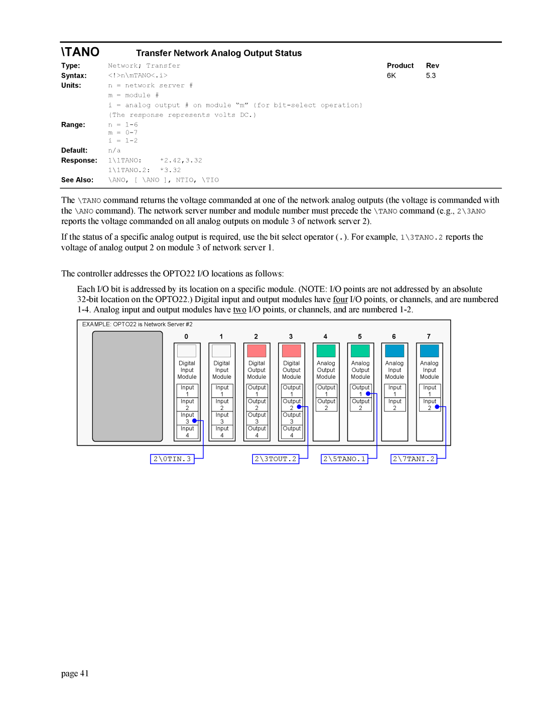
The controller addresses the OPTO22 I/O locations as follows:
Each I/O bit is addressed by its location on a specific module. (NOTE: I/O points are not addressed by an absolute
EXAMPLE: OPTO22 is Network Server #2
0 | 1 | 2 | 3 | 4 | 5 | 6 | 7 |
Digital | Digital | Digital | Digital | Analog | Analog | Analog | Analog |
Input | Input | Output | Output | Output | Output | Input | Input |
Module | Module | Module | Module | Module | Module | Module | Module |
Input | Input | Output | Output | Output | Output | Input | Input |
1 | 1 | 1 | 1 | 1 | 1 | 1 | 1 |
Input | Input | Output | Output | Output | Output | Input | Input |
2 | 2 | 2 | 2 | 2 | 2 | 2 | 2 |
Input | Input | Output | Output |
|
|
|
|
3 | 3 | 3 | 3 |
|
|
|
|
Input | Input | Output | Output |
|
|
|
|
4 | 4 | 4 | 4 |
|
|
|
|
2\0TIN.3 |
|
| 2\3TOUT.2 |
|
| 2\5TANO.1 |
|
| 2\7TANI.2 |
|
|
|
|
|
page 41
