Figure 5. Removing Chassis Cover
UNDERSTANDING THE DX8100 COMPONENT LAYOUT
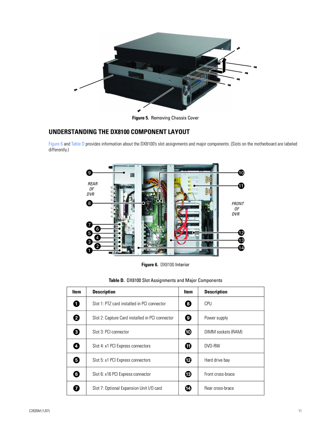
Figure 6 and Table D provides information about the DX8100’s slot assignments and major components. (Slots on the motherboard are labeled differently.)
REAR
OF
DVR
FRONT
OF
DVR
Figure 6. DX8100 Interior
Table D. DX8100 Slot Assignments and Major Components
Item | Description | Item | Description |
|
|
|
|
| Slot 1: PTZ card installed in PCI connector |
| CPU |
|
|
|
|
| Slot 2: Capture Card installed in PCI connector |
| Power supply |
|
|
|
|
| Slot 3: PCI connector |
| DIMM sockets (RAM) |
|
|
|
|
| Slot 4: x1 PCI Express connectors |
|
|
|
|
|
|
| Slot 5: x1 PCI Express connectors |
| Hard drive bay |
|
|
|
|
| Slot 6: x16 PCI Express connector |
| Front |
|
|
|
|
| Slot 7: Optional Expansion Unit I/O card |
| Rear |
|
|
|
|
C2635M (1/07) | 11 |