Pinnacle Design 37T100105 manual 28 Stereo Setting, 29 ,Four Logical Output Busses

Models: 37T100105

1 80
Download 80 pages 36.75 Kb
Page 32
Image 32
Figure 3-28: Stereo Setting

Chapter 3: Installation and Setup

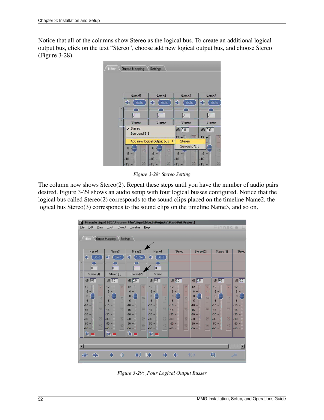
Notice that all of the columns show Stereo as the logical bus. To create an additional logical output bus, click on the text “Stereo”, choose add new logical output bus, and choose Stereo (Figure 3-28).

Figure 3-28: Stereo Setting

The column now shows Stereo(2). Repeat these steps until you have the number of audio pairs desired. Figure 3-29 shows an audio setup with four logical busses configured. Notice that the logical bus called Stereo(2) corresponds to the sound clips placed on the timeline Name2, the logical bus Stereo(3) corresponds to the sound clips on the timeline Name3, and so on.

Figure 3-29: ,Four Logical Output Busses

32

MMG Installation, Setup, and Operations Guide

Page 32
Image 32
Pinnacle Design 37T100105 manual 28 Stereo Setting, 29 ,Four Logical Output Busses