07-007 W-2WAY_II_NA 1/23/07 6:09 PM Page 82
Table of
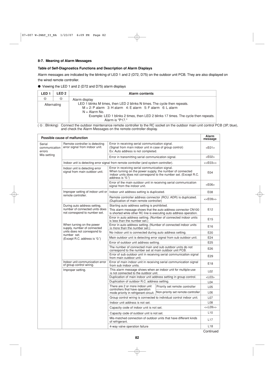
Alarm messages are indicated by the blinking of LED 1 and 2 (D72, D75) on the outdoor unit PCB. They are also displayed on
the wired remote controller.
●Viewing the LED 1 and 2 (D72 and D75) alarm displays
LED 1 |
| LED 2 |
| Alarm contents |
|
|
|
|
| ||
|
|
|
|
|
|
|
|
|
|
|
|
|
|
|
|
| Alarm display |
|
|
|
|
|
|
Alternating |
|
| LED 1 blinks M times, then LED 2 blinks N times. The cycle then repeats. |
|
|
|
| ||||
|
|
|
|
| M = 2: P alarm | 3: H alarm 4: E alarm 5: F alarm 6: L alarm |
|
|
|
| |
|
|
|
|
| N = Alarm No. |
|
|
|
|
|
|
|
|
|
|
| Example: LED 1 blinks 2 times, then LED 2 blinks 17 times. The cycle then repeats. |
| |||||
|
|
|
|
| Alarm is "P17." |
|
|
|
|
| |
|
|
|
|
| |||||||
( : Blinking) | Connect the outdoor maintenance remote controller to the RC socket on the outdoor main unit control PCB (3P, blue), | ||||||||||
|
|
| and check the Alarm Messages on the remote controller display. |
|
|
|
| ||||
|
|
|
|
|
|
|
|
|
|
|
|
Possible cause of malfunction |
|
| Alarm |
| |||||||
|
| message |
| ||||||||
Serial |
|
| Remote controller is detecting | Error in receiving serial communication signal. |
|
|
|
| |||
communication |
| error signal from indoor unit. | (Signal from main indoor unit in case of group control) | <E01> |
| ||||||
errors |
|
|
|
| Ex: Auto address is not completed. |
|
|
|
| ||
|
|
|
|
|
|
|
|
|
| ||
|
|
|
| Error in transmitting serial communication signal. | <E02> |
|
| ||||
|
|
|
|
|
|
| |||||
|
|
|
|
|
|
|
|
|
|
|
|
|
|
|
| Indoor unit is detecting error signal from remote controller (and system controller). | <<E03>> |
| |||||
|
|
|
|
|
|
|
|
|
|
|
|
|
|
|
| Indoor unit is detecting error | Error in receiving serial communication signal. |
|
|
|
| ||
|
|
|
| signal from main outdoor unit. | When turning on the power supply, the number of connected | E04 |
| ||||
|
|
|
|
|
| indoor units does not correspond to the number set. (Except R.C. |
|
|
|
| |
|
|
|
|
|
| address is “0.”) |
|
|
|
|
|
|
|
|
|
|
|
|
|
|
|
|
|
|
|
|
|
|
| Error of the main outdoor unit in receiving serial communication | <E06> |
|
| ||
|
|
|
|
|
| signal from the indoor unit. |
|
| |||
|
|
|
|
|
|
|
|
|
|
| |
|
|
|
|
|
|
|
|
|
|
|
|
|
|
|
| Improper setting of indoor unit or | Indoor unit address setting is duplicated. | E08 |
| ||||
|
|
|
| remote controller. |
|
|
|
|
|
| |
|
|
|
| Remote controller address connector (RCU. ADR) is duplicated. | <<E09>> |
|
| ||||
|
|
|
|
|
|
|
| ||||
|
|
|
|
|
| (Duplication of main remote controller) |
| ||||
|
|
|
|
|
|
|
|
|
| ||
|
|
|
|
|
|
|
|
|
|
|
|
|
|
|
| During auto address setting, | Starting auto address setting is prohibited. |
|
|
|
| ||
|
|
|
| number of connected units does | This alarm message shows that the auto address connector CN100 | E12 |
| ||||
|
|
|
| not correspond to number set. | is shorted while other RC line is executing auto address operation. |
|
|
|
| ||
|
|
|
|
|
|
|
|
|
|
|
|
|
|
|
|
|
| Error in auto address setting. (Number of connected indoor units | E15 |
|
| ||
|
|
|
|
|
| is less than the number set.) |
|
| |||
|
|
|
|
|
|
|
|
|
|
| |
|
|
|
| When turning on the power | Error in auto address setting. (Number of connected indoor units | E16 |
|
| |||
|
|
|
| supply, number of connected | is more than the number set.) |
|
| ||||
|
|
|
|
|
|
|
|
| |||
|
|
|
| units does not correspond to | No indoor unit is connected during auto address setting. | E20 |
|
| |||
|
|
|
| number set. |
| ||||||
|
|
|
|
|
|
|
|
|
| ||
|
|
|
| Main outdoor unit is detecting error signal from sub outdoor unit. | E24 |
|
| ||||
|
|
|
| (Except R.C. address is “0.”) |
| ||||||
|
|
|
|
|
|
|
|
|
| ||
|
|
|
|
|
| Error of outdoor unit address setting. | E25 |
| |||
|
|
|
|
|
|
|
|
|
|
|
|
|
|
|
|
|
| The number of connected main and sub outdoor units do not | E26 |
|
| ||
|
|
|
|
|
| correspond to the number set at main outdoor unit PCB. |
| ||||
|
|
|
|
|
|
|
|
|
| ||
|
|
|
|
|
| Error of sub outdoor unit in receiving serial communication signal | E29 |
|
| ||
|
|
|
|
|
| from main outdoor unit. |
|
| |||
|
|
|
|
|
|
|
|
|
|
| |
|
|
|
| Indoor unit communication error | Error of main indoor unit in receiving serial communication signal | E18 |
|
| |||
|
|
|
| of group control wiring. | from sub indoor units. |
|
| ||||
|
|
|
|
|
|
|
|
| |||
|
|
|
|
|
|
|
|
|
|
|
|
|
|
|
| Improper setting. | This alarm message shows when an indoor unit for | L02 |
|
| |||
|
|
|
|
|
| is not connected to the outdoor unit. |
| ||||
|
|
|
|
|
|
|
|
|
| ||
|
|
|
|
|
| Duplication of main indoor unit address setting in group control. | <L03> |
| |||
|
|
|
|
|
| Duplication of outdoor R.C. address setting. | L04 |
| |||
|
|
|
|
|
| There are 2 or more indoor unit | Priority set remote controller | L05 |
| ||
|
|
|
|
|
| controllers that have operation |
|
|
|
|
|
|
|
|
|
|
| L06 |
|
| |||
|
|
|
|
|
| mode priority in refrigerant circuit. |
| ||||
|
|
|
|
|
|
|
|
|
|
| |
|
|
|
|
|
| Group control wiring is connected to individual control indoor unit. | L07 |
| |||
|
|
|
|
|
|
|
|
|
|
| |
|
|
|
|
|
| Indoor unit address is not set. |
| L08 |
| ||
|
|
|
|
|
|
|
|
|
| ||
|
|
|
|
|
| Capacity code of indoor unit is not set. | <<L09>> |
| |||
|
|
|
|
|
|
|
|
|
| ||
|
|
|
|
|
| Capacity code of outdoor unit is not set. | L10 |
| |||
|
|
|
|
|
| L17 |
|
| |||
|
|
|
|
|
| of refrigerant. |
|
| |||
|
|
|
|
|
|
|
|
|
|
| |
|
|
|
|
|
|
|
|
|
|
| |
|
|
|
|
|
|
| L18 |
| |||
|
|
|
|
|
|
|
|
|
|
|
|
|
|
|
|
|
|
|
| Continued | |||
82