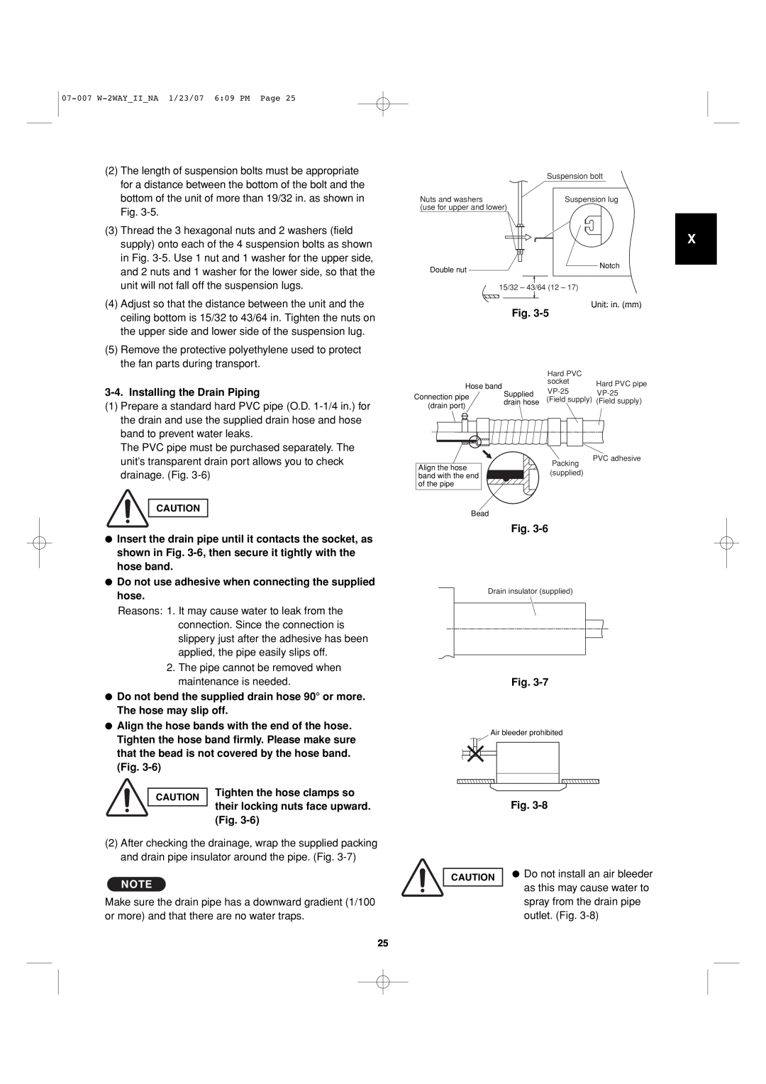
(2) | The length of suspension bolts must be appropriate |
| for a distance between the bottom of the bolt and the |
| bottom of the unit of more than 19/32 in. as shown in |
| Fig. |
(3) | Thread the 3 hexagonal nuts and 2 washers (field |
| Suspension bolt |
|
Nuts and washers | Suspension lug | |
(use for upper and lower) |
|
|
supply) onto each of the 4 suspension bolts as shown |
in Fig. |
and 2 nuts and 1 washer for the lower side, so that the |
Double nut
X
Notch
| unit will not fall off the suspension lugs. |
(4) | Adjust so that the distance between the unit and the |
| ceiling bottom is 15/32 to 43/64 in. Tighten the nuts on |
| the upper side and lower side of the suspension lug. |
(5) | Remove the protective polyethylene used to protect |
| the fan parts during transport. |
3-4. Installing the Drain Piping
(1) Prepare a standard hard PVC pipe (O.D. |
the drain and use the supplied drain hose and hose |
band to prevent water leaks. |
The PVC pipe must be purchased separately. The |
15/32 – 43/64 (12 – 17)
Unit: in. (mm)
Fig.
|
|
|
|
|
|
| Hard PVC |
| |||
| Hose band |
| socket | Hard PVC pipe | |||||||
|
| ||||||||||
| Supplied | ||||||||||
Connection pipe | |||||||||||
drain hose | (Field supply) | (Field supply) | |||||||||
(drain port) | |||||||||||
|
|
|
|
| |||||||
|
|
|
|
|
|
|
|
|
|
| |
|
|
|
|
|
|
|
|
|
|
| |
|
|
|
|
|
|
|
|
|
|
| |
|
|
|
|
|
|
|
|
|
|
| |
|
|
|
|
|
|
|
|
|
|
| |
|
|
|
|
|
|
|
|
|
|
| |
unit’s transparent drain port allows you to check |
Align the hose
Packing
PVC adhesive
drainage. (Fig. |
CAUTION
●Insert the drain pipe until it contacts the socket, as shown in Fig.
●Do not use adhesive when connecting the supplied hose.
Reasons: 1. It may cause water to leak from the connection. Since the connection is slippery just after the adhesive has been applied, the pipe easily slips off.
2.The pipe cannot be removed when maintenance is needed.
●Do not bend the supplied drain hose 90° or more. The hose may slip off.
●Align the hose bands with the end of the hose. Tighten the hose band firmly. Please make sure that the bead is not covered by the hose band. (Fig.
CAUTION | Tighten the hose clamps so | |
their locking nuts face upward. | ||
| ||
| ||
| (Fig. |
(2)After checking the drainage, wrap the supplied packing and drain pipe insulator around the pipe. (Fig.
NOTE
Make sure the drain pipe has a downward gradient (1/100 or more) and that there are no water traps.
band with the end(supplied) of the pipe
Bead
Fig.
Drain insulator (supplied)
Fig.
Air bleeder prohibited
Fig.
CAUTION | ● Do not install an air bleeder | |
as this may cause water to | ||
| ||
| ||
| spray from the drain pipe | |
| outlet. (Fig. |
25