Optional Controllers
R410A Models Indoor Units
Outdoor Units
Gunma, Japan
…In an Area with High Winds
…In a Room
…In Moist or Uneven Locations
…In a Snowy Area for Heat Pump-type Systems
Check of Density Limit
Different tools required
Care regarding tubing
Be sure to recharge the refrigerant only in liquid form
New
Single-outlet valve
Compressor specifications are different
Use R410A exclusive cylinder only
Existing tubing cannot be used especially R22
Contents
Air Purging with a Vacuum Pump for Test Run Preparation
HOW to Process Tubing
AIR Purging
Test RUN
’ty
General
Outdoor Unit Part name
Model 10 hp 16 hp
4-Way Air Discharge Semi-Concealed
1-Way Air Discharge Semi-Concealed
Concealed Duct
Concealed Duct High-Static Pressure
Ceiling-Mounted
Wall-Mounted
Contents
Mark
Length ft
11 Outdoor Unit Tubing Connection Size a BTU/h
Tubing Size Main Tubing Size LA
10 Main Tubing Size After Distribution LB, LC
28.0 45.0
Additional Refrigerant Charge
Straight Equivalent Length of Joints
13 Straight Equivalent Length of Joints
16 Refrigerant Charge Amount at Shipment for outdoor unit
When using ball valve
When not using ball valve
Tube branching methods horizontal use
Tubing size with thermal insulation
Optional Distribution Joint Kits
Model name Cooling capacity after distribution Remarks
Example
232,000 BTU/h 68.0 kW
Example
Main tubing Distribution joint tubing
Main tubing
Front view
Selecting the Installation Site
Indoor Unit
Side view
Leave space open above
Installation Space
Outdoor Unit
Unit
Precautions When Installing in Heavy Snow Areas
Shield for Horizontal Exhaust Discharge
Unit installation
Air direction Front direction
Air direction
12, 18, 24
Suspending the Indoor Unit
Placing the Unit Inside the Ceiling
12, 18
Installing the Drain Piping
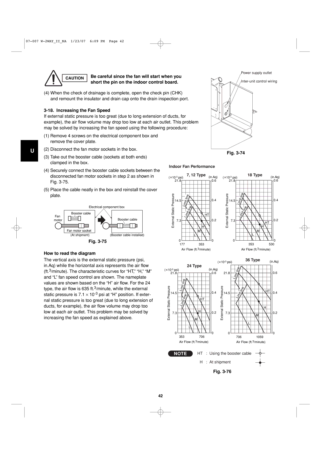
Start when you short the pin
Be careful since the fan will
On the indoor control board
Removing the corner cover
Attached tightly to the unit. Fig
Installing the Ceiling Panel
Panel installation locations so that the panel is
Check that the panel is attached tightly to
Wiring the Ceiling Panel
Adjusting the Auto Flap
Checking After Installation
When Removing the Ceiling Panel for Servicing
Special Remarks DC Fan Tap Change Procedure
29/64
Full-scale Installation diagram Suspension lug 25/32 1
Installing the Drain Piping
Control board
When you short the pin on the indoor
Be careful since the fan will start
Bottom drain port is for use only
Appearance Part name
Electrical Power Wiring Wiring connections
Wiring
Appearance
Removing the intake grille
Removing the side panel
Adjust so that there is no gap
Other Check after installation
Installing the side panel and intake grille
Installing the intake grille
If a wireless remote controller is used
62 and -4 show the detailed dimensions of the indoor unit
Type Length
Tubing must be laid and connected inside the ceiling when
Suspension bolts referring to the dimensional data on
Previous page. -61 and Table
Unit inside the ceiling
Do not use the supplied drain hose bent at a 90 angle
Do not use adhesive at the drain connection port on
Indoor unit
Maximum permissible bend is
Short the pin on the indoor control board
Be careful since the fan will start when you
How to read the diagram
Increasing the Fan Speed
So that the indoor unit and ducts are not visible. Only
This air conditioner is usually installed above the ceiling
Minimum space for installation and service is shown
Air intake and air outlet ports are visible from below
Supporting the indoor unit inside
Enough to suport the weight of the unit
It is important that you use extreme care
Ceiling. Ensure that the ceiling is strong
Indoor Fan Performance How to Read the Diagram
Service
Refrigerant tubing drain hose position
It is important that you use
Weight of the unit. Before
Wall and ceiling side opening position
Extreme care in supporting
Inside
Duct for Fresh Air
Shaping the Tubing
Rear outlet port
Regulations before wiring
How to carry out power supply wiring
When removing the fastening
Bracket from the cover
Selecting and Making a Hole
Removing the grille
Removing the Grille to Install the Indoor Unit
If the Wall is Brick, Concrete or Similar
Attaching the grille
Left or left-rear tubing
Installing the Drain Hose
Shaping the Tubing Right-rear tubing
Unit are completed
KHX0752 / 0952 / 1252
HOW to Install the Outdoor Unit
Installing the Outdoor Unit
Transporting
Routing the Tubing
Prepare the Tubing
Connect the Tubing
Refrigerant tubing Connection method Supplied parts used?
Work method
Refrigerant tube port
Tightening torque for each cap
Cap tightening torque
Electrical Wiring
General Precautions on Wiring
Inter-outdoor unit control wiring
Wiring System Diagram
U, D, T Type
Outdoor unit Indoor unit
How to connect wiring to the terminal For stranded wiring
Shielded wire GroundGround
Flaring Procedure with a Flare Tool
HOW to Process Tubing
Connecting the Refrigerant Tubing Use of the Flaring Method
Deburring
Tube diameter Tightening torque Tube thickness Approximate
870 Lbs · inch Over 5/128 1000 1200 kgf · cm
Insulating the Refrigerant Tubing Tubing Insulation
Two tubes arranged together
Three tubes arranged together
Insulation material
Finishing the Installation
Taping the Tubes
Leak test
Bottom when you pressurize
Air Purging with a Vacuum Pump for Test Run Preparation
Use a manifold valve for air purging
Evacuation
45 min. or more 90 min. or more
Use a cylinder designed for use With R410A respectively
Charging additional refrigerant
Finishing the job
Test RUN
Test Run Procedure
Items to Check Before the Test Run
Main Outdoor Unit PCB Setting
3P DIP switch, blue
Indoor unit setting S004 Rotary switch, red
Examples of the No. of outdoor units settings S006
Address setting of main outdoor unit S007 Unit No. setting
Auto Address Setting Basic wiring diagram Example
Automatic Address Setting from the Outdoor Unit
Case
22-9
Case 2 Automatic Address Setting no compressor operation
Automatic Address Setting from Outdoor Unit
Automatic Address Setting in Heating Mode
Automatic Address Setting from Outdoor Unit
Case 3A
Automatic Address Setting in Cooling Mode
Automatic Address Setting* from the Remote Controller
Case 3B
Display during automatic address setting
On outdoor main unit PCB
If 1 indoor unit is connected to 1 remote controller
Remote Controller Test Run Settings
Checking the indoor unit addresses
07-007 W-2WAYIINA 1/23/07 609 PM
Alarm contents
Possible cause of malfunction
Alarm
Alarm messages displayed on system controller
Care and Cleaning
Appendix
Name of Parts
Latch Air intake Safety chain Grille Bolt screws
Troubleshooting
Should the power fail while the unit is running
Tips for Energy Saving
Type 1-WAY
Water drain Air outlet Air intake Ceiling panel optional
Troubleshooting
Concealed Duct High-Static Pressure Type U, D Type
Type standard static pressure Type high static pressure
Troubleshooting
Components and cause an electric shock hazard
Air intake grille air intake
Or soot
Type Wall-Mounted
Tips for Energy Saving