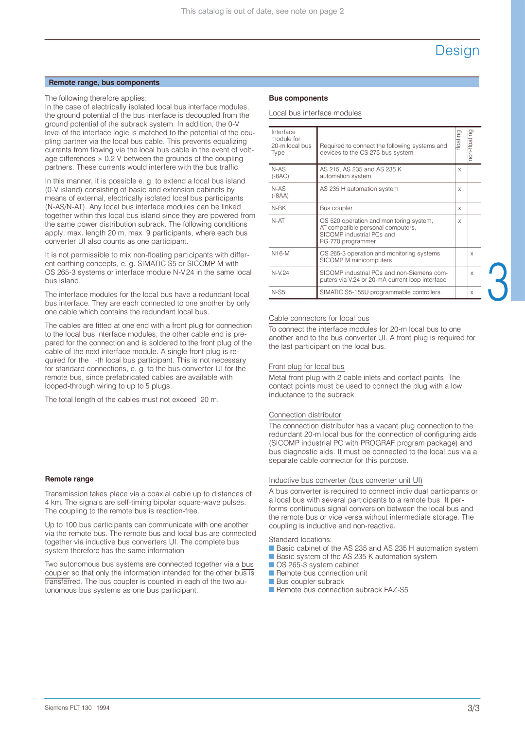
This catalog is out of date, see note on page 2
Design
Remote range, bus components
The following therefore applies:
In the case of electrically isolated local bus interface modules, the ground potential of the bus interface is decoupled from the ground potential of the subrack system. In addition, the
In this manner, it is possible e. g. to extend a local bus island
It is not permissible to mix
The interface modules for the local bus have a redundant local bus interface. They are each connected to one another by only one cable which contains the redundant local bus.
The cables are fitted at one end with a front plug for connection to the local bus interface modules, the other cable end is pre- pared for the connection and is soldered to the front plug of the cable of the next interface module. A single front plug is re- quired for the
The total length of the cables must not exceed 20 m.
Remote range
Transmission takes place via a coaxial cable up to distances of 4 km. The signals are
Up to 100 bus participants can communicate with one another via the remote bus. The remote bus and local bus are connected together via inductive bus converters UI. The complete bus system therefore has the same information.
Two autonomous bus systems are connected together via a bus coupler so that only the information intended for the other bus is transferred. The bus coupler is counted in each of the two au- tonomous bus systems as one bus participant.
Bus components
Local bus interface modules
Interface |
| floating | floatingnon- |
module for |
|
|
|
Required to connect the following systems and |
|
| |
Type | devices to the CS 275 bus system |
|
|
|
|
|
|
AS 215, AS 235 and AS 235 K | x |
| |
automation system |
|
| |
|
|
|
|
AS 235 H automation system | x |
| |
|
|
| |
|
|
|
|
Bus coupler | x |
| |
|
|
|
|
OS 520 operation and monitoring system, | x |
| |
|
|
| |
| SICOMP industrial PCs and |
|
|
| PG 770 programmer |
|
|
|
|
|
|
OS |
| x | |
| SICOMP M minicomputers |
|
|
|
|
|
|
SICOMP industrial PCs and |
| x | |
| puters via V.24 or |
|
|
|
|
|
|
SIMATIC |
| x | |
|
|
|
|
Cable connectors for local bus
To connect the interface modules for
Front plug for local bus
Metal front plug with 2 cable inlets and contact points. The contact points must be used to connect the plug with a low inductance to the subrack.
Connection distributor
The connection distributor has a vacant plug connection to the redundant
Inductive bus converter (bus converter unit UI)
A bus converter is required to connect individual participants or a local bus with several participants to a remote bus. It per- forms continuous signal conversion between the local bus and the remote bus or vice versa without intermediate storage. The coupling is inductive and
Standard locations:
![]() Basic cabinet of the AS 235 and AS 235 H automation system
Basic cabinet of the AS 235 and AS 235 H automation system
![]() Basic system of the AS 235 K automation system
Basic system of the AS 235 K automation system
![]() OS
OS ![]() Remote bus connection unit
Remote bus connection unit
![]() Bus coupler subrack
Bus coupler subrack
![]() Remote bus connection subrack
Remote bus connection subrack
Siemens PLT 130 . 1994 | 3/3 |
