This catalog is out of date, see note on page 2
Design
General notes, local range
The CS 275 bus system is physically divided into
Each participant requires a local bus interface module to enable bus communication, redundant systems such as the AS 235 H automation system require two modules. These interface mod- ules convert the various internal system bus interfaces of the participants into the uniform local bus interface. The transfer control function for the complete bus is transferred from partici- pant to participant. This function is also handled by the local bus interface module of the respective participant which cur- rently possesses the master function.
The design of the local bus interface modules depends on the participant system to be connected. Thus the modules e. g. for connection of the automation systems are of double ”EUROPE” format, and those for connection of SICOMP industral PCs are of AT format. In the local range, the local bus interface modules are connected together into a ”local bus island” using cables.
Systems not belonging to TELEPERM M require additional cou- pling software to match their internal communication interface to that of the CS 275 bus system. This software is available, amongst others, for the connection of personal computers with
In the remote range, individual participants or complete local bus islands are connected to the remote bus via inductive bus couplers UI. Different designs of coaxial cable are available for the connection depending on the associated mechanical stress.
The local bus is always redundant, the remote bus can be either single or redundant.
Local range
The transmission is on
Three line signals are used. The data themselves are trans- mitted sequentially on one data line. A second line transmits the clock, the third is used for synchronization.
It is necessary to differentiate between electrical participants and (bus) participants when determining the maximum possible number of participants. Electrical participants are the local bus interface modules, the bus converter modules UI and connec- tion multiplexers AV (for connection of a local bus interface module).
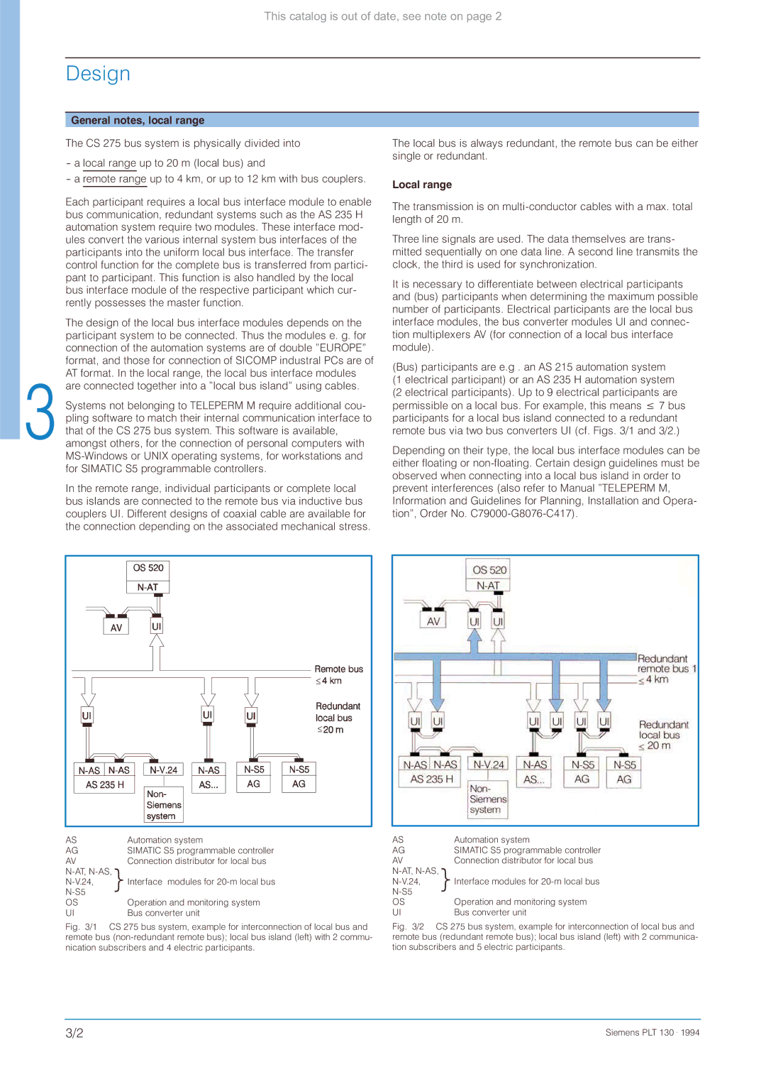
(Bus) participants are e.g . an AS 215 automation system (1 electrical participant) or an AS 235 H automation system (2 electrical participants). Up to 9 electrical participants are permissible on a local bus. For example, this means 7 bus participants for a local bus island connected to a redundant remote bus via two bus converters UI (cf. Figs. 3/1 and 3/2.)
Depending on their type, the local bus interface modules can be either floating or
≤![]()
![]()
≤![]()
![]()
AS | Automation system |
AG | SIMATIC S5 programmable controller |
AV | Connection distributor for local bus |
} Interface modules for | |
| |
OS | Operation and monitoring system |
UI | Bus converter unit |
Fig. 3/1 CS 275 bus system, example for interconnection of local bus and remote bus (non-redundant remote bus); local bus island (left) with 2 commu- nication subscribers and 4 electric participants.
AS | Automation system |
AG | SIMATIC S5 programmable controller |
AV | Connection distributor for local bus |
} Interface modules for | |
| |
OS | Operation and monitoring system |
UI | Bus converter unit |
Fig. 3/2 CS 275 bus system, example for interconnection of local bus and remote bus (redundant remote bus); local bus island (left) with 2 communica- tion subscribers and 5 electric participants.
3/2 | Siemens PLT 130 . 1994 |