This catalog is out of date, see note on page 2
Design
Bus components
Connector board AF
The remote bus cable is connected to the bus converter via the connector board AF.
The board is provided with a terminating resistor which can be activated using a jumper. The resistor is activated in the con- nector board of the first and last bus participants (Fig. 3/3).
Standard locations:
![]() Basic cabinet of the AS 235 and AS 235 H automation sy- stems
Basic cabinet of the AS 235 and AS 235 H automation sy- stems
![]() Basic system of the AS 235 K automation system
Basic system of the AS 235 K automation system
![]() OS
OS ![]() Remote bus connection unit.
Remote bus connection unit.
Bus coupler
Autonomous buses are connected together via a bus coupler. Data transfer is then possible between several systems or sys- tem areas over larger distances (> 4 km) with decoupling of the data traffic on the buses.
The intermediate connection of up to 2 bus couplers is permissi- ble for data transfer between any two participants in the com- plete bus system.
Two different structures are possible when designing a bus sy- stem with bus couplers:
![]() Line structure
Line structure ![]() Hierarchical structure.
Hierarchical structure.
![]() ≤
≤![]()
![]()
![]()
![]()
![]()
≤ ![]()
![]()
![]()
BK Bus coupler
Fig. 3/4 Bus system with linear structure
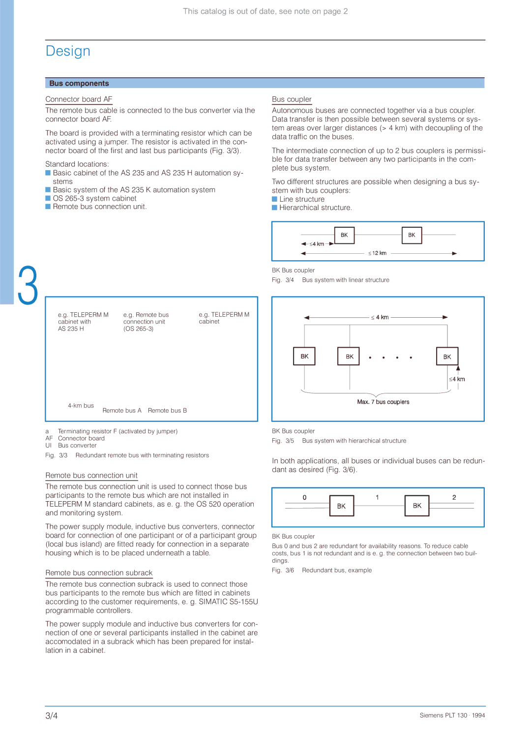
e.g. TELEPERM M | e.g. Remote bus | e.g. TELEPERM M |
cabinet with | connection unit | cabinet |
AS 235 H | (OS |
|
|
|
Remote bus A Remote bus B
aTerminating resistor F (activated by jumper) AF Connector board
UI Bus converter
Fig. 3/3 Redundant remote bus with terminating resistors
Remote bus connection unit
The remote bus connection unit is used to connect those bus participants to the remote bus which are not installed in TELEPERM M standard cabinets, as e. g. the OS 520 operation and monitoring system.
The power supply module, inductive bus converters, connector board for connection of one participant or of a participant group (local bus island) are fitted ready for connection in a separate housing which is to be placed underneath a table.
Remote bus connection subrack
≤ |
≤ |
BK Bus coupler
Fig. 3/5 Bus system with hierarchical structure
In both applications, all buses or individual buses can be redun- dant as desired (Fig. 3/6).
BK Bus coupler
Bus 0 and bus 2 are redundant for availability reasons. To reduce cable costs, bus 1 is not redundant and is e. g. the connection between two buil- dings.
Fig. 3/6 Redundant bus, example
The remote bus connection subrack is used to connect those bus participants to the remote bus which are fitted in cabinets according to the customer requirements, e. g. SIMATIC
The power supply module and inductive bus converters for con- nection of one or several participants installed in the cabinet are accomodated in a subrack which has been prepared for instal- lation in a cabinet.
3/4 | Siemens PLT 130 . 1994 |