This catalog is out of date, see note on page 2
Design
Bus components, technical data
Overvoltage protection
The participants connected to the remote bus can be exten- sively protected against destruction by overvoltages by means of the coarse and fine overvoltage protection units.
The coarse protection limits
Remote bus cable
Standard coaxial cable is used as the remote bus cable. This may be routed in potentially explosive atmospheres to
DIN 57 165/VDE 0165, Section 5.6.1. It is also suitable for burial in the ground. The max. permissible length is 4000 m.
An
An increased tensile strength up to 25 000 N is possible using a cable with additional armouring. If protection against damage by rodents and mechanical damage is required, the cable with additional
Connection of remote bus cables
It may be necessary when using remote bus cables to connect sections together. The maximum available length of the
The type of connection depends on the type of cable. Standard and
To provide protection against mechanical damage, the connec- tion should be enclosed in a metal sleeve. The cable armouring can be electrically connected using a copper cable (e. g. as additional overvoltage protection) and secured to prevent ten- sion. The sleeve is filled with sealing compound following as- sembly. All parts required can be obtained as a parts kit for splicing coaxial cables.
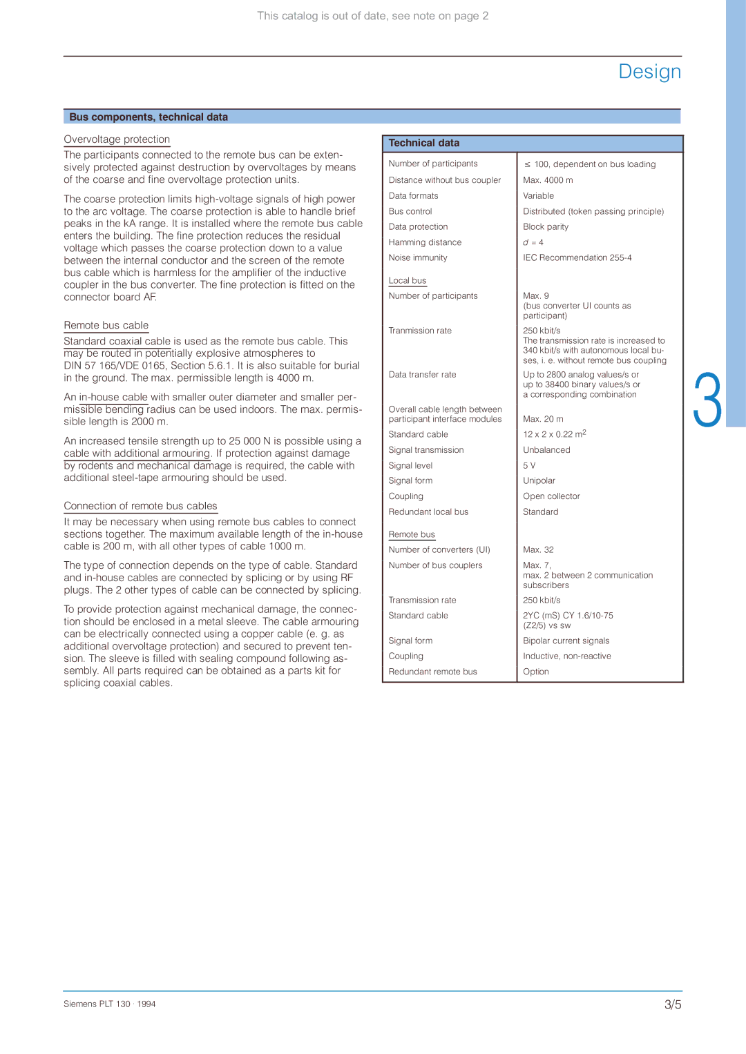
Technical data
Number of participants | 100, dependent on bus loading | |||
Distance without bus coupler | Max. 4000 m | |||
Data formats | Variable | |||
Bus control | Distributed (token passing principle) | |||
Data protection | Block parity | |||
Hamming distance | d = 4 | |||
Noise immunity | IEC Recommendation | |||
Local bus |
| |||
|
|
|
|
|
Number of participants | Max. 9 | |||
|
|
|
| (bus converter UI counts as |
|
|
|
| participant) |
Tranmission rate | 250 kbit/s | |||
|
|
|
| The transmission rate is increased to |
|
|
|
| 340 kbit/s with autonomous local bu- |
|
|
|
| ses, i. e. without remote bus coupling |
Data transfer rate | Up to 2800 analog values/s or | |||
|
|
|
| up to 38400 binary values/s or |
|
|
|
| a corresponding combination |
Overall cable length between |
| |||
participant interface modules | Max. 20 m | |||
Standard cable | 12 x 2 x 0.22 m2 | |||
Signal transmission | Unbalanced | |||
Signal level | 5 V | |||
Signal form | Unipolar | |||
Coupling | Open collector | |||
Redundant local bus | Standard | |||
Remote bus |
| |||
|
|
|
|
|
Number of converters (UI) | Max. 32 | |||
Number of bus couplers | Max. 7, | |||
|
|
|
| max. 2 between 2 communication |
|
|
|
| subscribers |
Transmission rate | 250 kbit/s | |||
Standard cable | 2YC (mS) CY | |||
|
|
|
| (Z2/5) vs sw |
Signal form | Bipolar current signals | |||
Coupling | Inductive, | |||
Redundant remote bus | Option | |||
|
|
|
|
|
Siemens PLT 130 . 1994 | 3/5 |
