This catalog is out of date, see note on page 2
Interface module for 20-m local bus (N-S5)
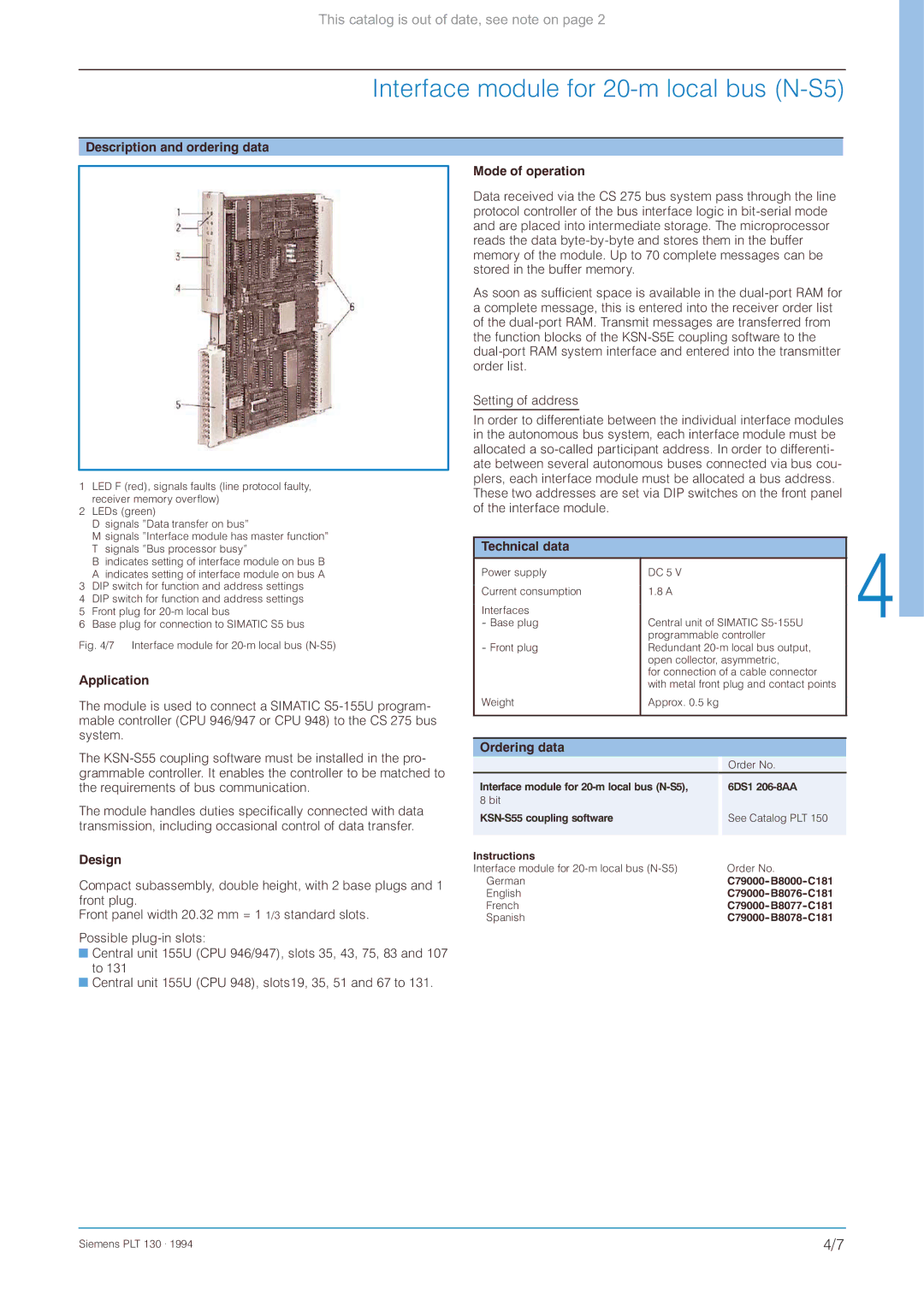
Description and ordering data
1 LED F (red), signals faults (line protocol faulty, receiver memory overflow)
2LEDs (green)
D signals ”Data transfer on bus”
M signals ”Interface module has master function” T signals ”Bus processor busy”
B indicates setting of interface module on bus B
A indicates setting of interface module on bus A
3DIP switch for function and address settings
4 DIP switch for function and address settings
5 Front plug for
6 Base plug for connection to SIMATIC S5 bus
Fig. 4/7 Interface module for 20-m local bus (N-S5)
Application
The module is used to connect a SIMATIC
The
The module handles duties specifically connected with data transmission, including occasional control of data transfer.
Design
Compact subassembly, double height, with 2 base plugs and 1 front plug.
Front panel width 20.32 mm = 1 1/3 standard slots.
Possible
![]() Central unit 155U (CPU 946/947), slots 35, 43, 75, 83 and 107 to 131
Central unit 155U (CPU 946/947), slots 35, 43, 75, 83 and 107 to 131
![]() Central unit 155U (CPU 948), slots19, 35, 51 and 67 to 131.
Central unit 155U (CPU 948), slots19, 35, 51 and 67 to 131.
Mode of operation
Data received via the CS 275 bus system pass through the line protocol controller of the bus interface logic in
As soon as sufficient space is available in the
Setting of address
In order to differentiate between the individual interface modules in the autonomous bus system, each interface module must be allocated a
Technical data |
|
|
|
|
Power supply | DC 5 V |
|
| |
Current consumption | 1.8 A |
|
| |
Interfaces | Central unit of SIMATIC |
| ||
- Base plug |
| |||
- Front plug | programmable controller |
| ||
Redundant |
| |||
| open collector, asymmetric, |
| ||
| for connection of a cable connector |
| ||
| with metal front plug and contact points |
| ||
Weight | Approx. 0.5 kg |
|
| |
|
|
|
|
|
|
|
|
|
|
Ordering data |
|
|
|
|
|
|
| Order No. |
|
Interface module for |
| 6DS1 |
| |
8 bit |
|
|
|
|
|
| See Catalog PLT 150 |
| |
|
|
| ||
|
|
|
|
|
Instructions |
|
|
|
|
Interface module for | Order No. |
| ||
German |
|
|
| |
English |
|
|
| |
French |
|
|
| |
Spanish |
|
|
| |
Siemens PLT 130 . 1994 | 4/7 |