This catalog is out of date, see note on page 2
Remote bus connection unit FAE
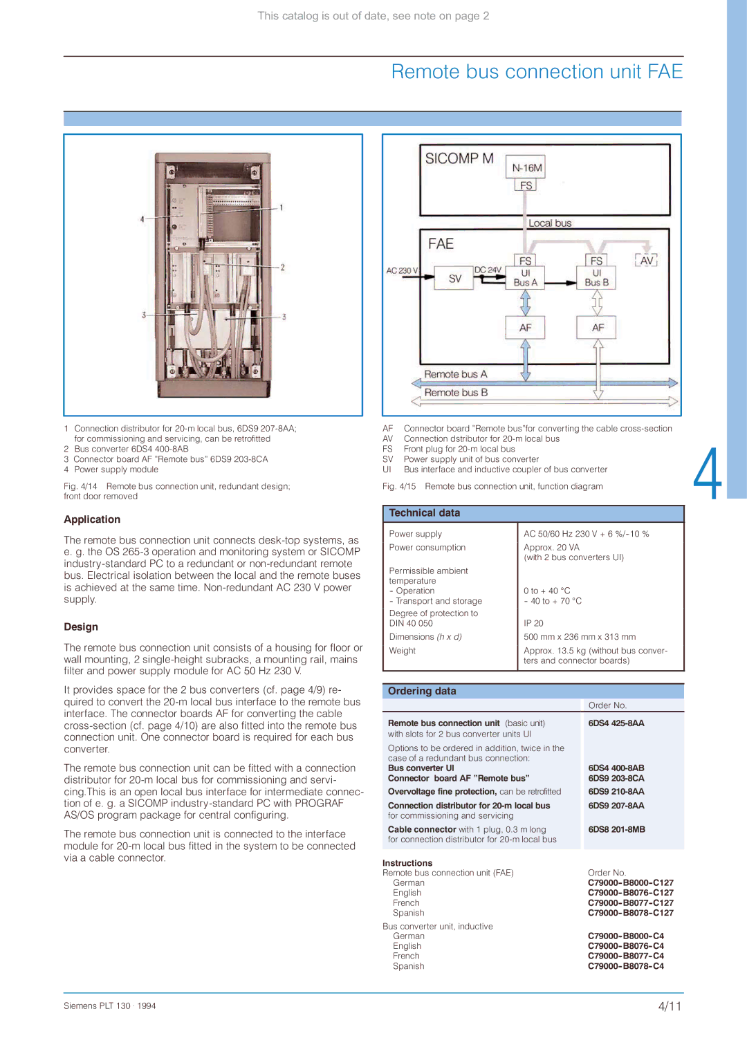
1 Connection distributor for
2 Bus converter 6DS4 400-8AB
3Connector board AF ”Remote bus” 6DS9
4 Power supply module
Fig. 4/14 Remote bus connection unit, redundant design; front door removed
Application
The remote bus connection unit connects
Design
The remote bus connection unit consists of a housing for floor or wall mounting, 2
It provides space for the 2 bus converters (cf. page 4/9) re- quired to convert the
The remote bus connection unit can be fitted with a connection distributor for
The remote bus connection unit is connected to the interface module for
AF | Connector board ”Remote bus”for converting the cable |
AV | Connection dstributor for |
FS | Front plug for |
SV | Power supply unit of bus converter |
UI | Bus interface and inductive coupler of bus converter |
Fig. 4/15 Remote bus connection unit, function diagram
Technical data |
|
|
|
|
Power supply | AC 50/60 Hz 230 V + 6 |
| ||
Power consumption | Approx. 20 VA |
|
| |
| (with 2 bus converters UI) |
| ||
Permissible ambient |
|
|
|
|
temperature | 0 to + 40 qC |
|
| |
- Operation |
|
| ||
- Transport and storage | - 40 to + 70 qC |
|
| |
Degree of protection to | IP 20 |
|
| |
DIN 40 050 |
|
| ||
Dimensions (h x d) | 500 mm x 236 mm x 313 mm |
| ||
Weight | Approx. 13.5 kg (without bus conver- |
| ||
| ters and connector boards) |
| ||
|
|
|
|
|
|
|
|
|
|
Ordering data |
|
|
|
|
|
|
| Order No. |
|
Remote bus connection unit (basic unit) |
| 6DS4 |
| |
with slots for 2 bus converter units Ul |
|
|
| |
|
|
|
| |
Options to be ordered in addition, twice in the |
|
| ||
case of a redundant bus connection: | 6DS4 |
| ||
Bus converter Ul |
|
|
| |
Connector board AF ”Remote bus” | 6DS9 |
| ||
|
|
| ||
Overvoltage fine protection, can be retrofitted |
| 6DS9 |
| |
|
|
|
| |
Connection distributor for | 6DS9 |
| ||
for commissioning and servicing |
|
|
|
|
Cable connector with 1 plug, 0.3 m long | 6DS8 |
| ||
for connection distributor for |
|
| ||
|
|
|
|
|
Instructions |
|
|
|
|
Remote bus connection unit (FAE) |
|
| Order No. |
|
German |
|
|
| |
English |
|
|
| |
French |
|
|
| |
Spanish |
|
|
| |
Bus converter unit, inductive |
|
|
|
|
German |
|
|
| |
English |
|
|
| |
French |
|
|
| |
Spanish |
|
|
| |
Siemens PLT 130 . 1994 | 4/11 |