This catalog is out of date, see note on page 2
Mode of operation
Redundant operation mode, transmission reliability, synchronization
Redundant operation mode
The CS 275 bus system can be redundant in order to increase the availability. The interface modules for the local bus are al- ready designed for a redundant local bus line. A bus converter UI and a connector board AF are required for connection of a redundant remote bus per remote bus cable. Different remote bus cable lengths are permissible between bus A and the re- dundant bus B.
The bus system is started up on bus A. Besides this, no prefer- ence is given to either bus. The bus system carries out a cyclic test to see whether a changeover criterion is satisfied. An auto- matic changeover is carried out if this is the case.
Changeover criteria
![]() An image of the local bus is generated through each bus line approx. every 750 ms. If the image of the passive bus con- tains more entries than that of the active bus, the system switches to the passive bus.
An image of the local bus is generated through each bus line approx. every 750 ms. If the image of the passive bus con- tains more entries than that of the active bus, the system switches to the passive bus.
![]() If the images on the two bus lines are the same, but the mas- ter detects a transfer request on the passive bus, a change- over also takes place to the passive bus. A slave sends trans- fer requests on the passive bus if transfers are no longer possible for it on the active bus.
If the images on the two bus lines are the same, but the mas- ter detects a transfer request on the passive bus, a change- over also takes place to the passive bus. A slave sends trans- fer requests on the passive bus if transfers are no longer possible for it on the active bus.
![]() If the current master fails because of a fault, the slave with the smallest participant address assumes the master function on the previously passive bus (if one exists).
If the current master fails because of a fault, the slave with the smallest participant address assumes the master function on the previously passive bus (if one exists).
The bus changeover is signalled to all bus participants.
Time synchronization
The
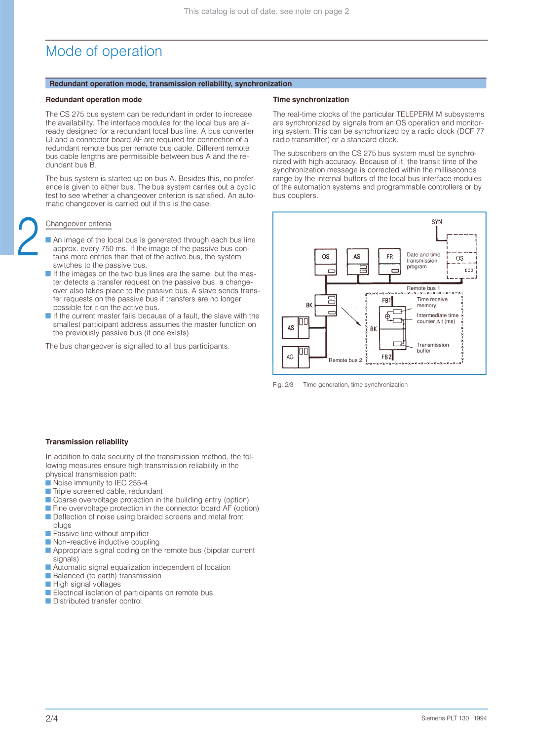
The subscribers on the CS 275 bus system must be synchro- nized with high accuracy. Because of it, the transit time of the synchronization message is corrected within the milliseconds range by the internal buffers of the local bus interface modules of the automation systems and programmable controllers or by bus couplers.
Date and time transmission program
Remote bus 1
Time receive memory
Intermediate time counter ' t (ms)
Transmission buffer
Remote bus 2
Fig. 2/3 Time generation, time synchronization
Transmission reliability
In addition to data security of the transmission method, the fol- lowing measures ensure high transmission reliability in the physical transmission path:
![]() Noise immunity to IEC
Noise immunity to IEC ![]() Triple screened cable, redundant
Triple screened cable, redundant
![]() Coarse overvoltage protection in the building entry (option)
Coarse overvoltage protection in the building entry (option)
![]() Fine overvoltage protection in the connector board AF (option)
Fine overvoltage protection in the connector board AF (option)
![]() Deflection of noise using braided screens and metal front plugs
Deflection of noise using braided screens and metal front plugs
![]() Passive line without amplifier
Passive line without amplifier
![]()
![]() Appropriate signal coding on the remote bus (bipolar current signals)
Appropriate signal coding on the remote bus (bipolar current signals)
![]() Automatic signal equalization independent of location
Automatic signal equalization independent of location ![]() Balanced (to earth) transmission
Balanced (to earth) transmission
![]() High signal voltages
High signal voltages
![]() Electrical isolation of participants on remote bus
Electrical isolation of participants on remote bus ![]() Distributed transfer control.
Distributed transfer control.
2/4 | Siemens PLT 130 . 1994 |